Mercury dispensing compositions and manufacturing process thereof
a technology of compositions and mercury, applied in the direction of gas-filled discharge tubes, liquid transferring devices, x-ray tubes, etc., can solve the problems of unable to provide exact and reproducible dosing, and reducing the work efficiency of workers,
- Summary
- Abstract
- Description
- Claims
- Application Information
AI Technical Summary
Benefits of technology
Problems solved by technology
Method used
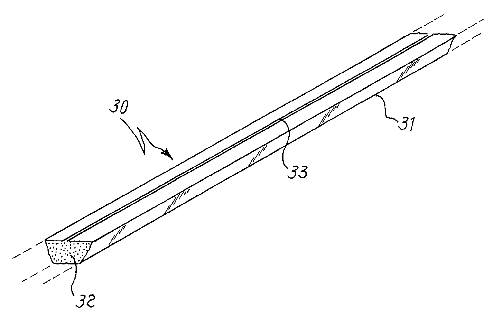
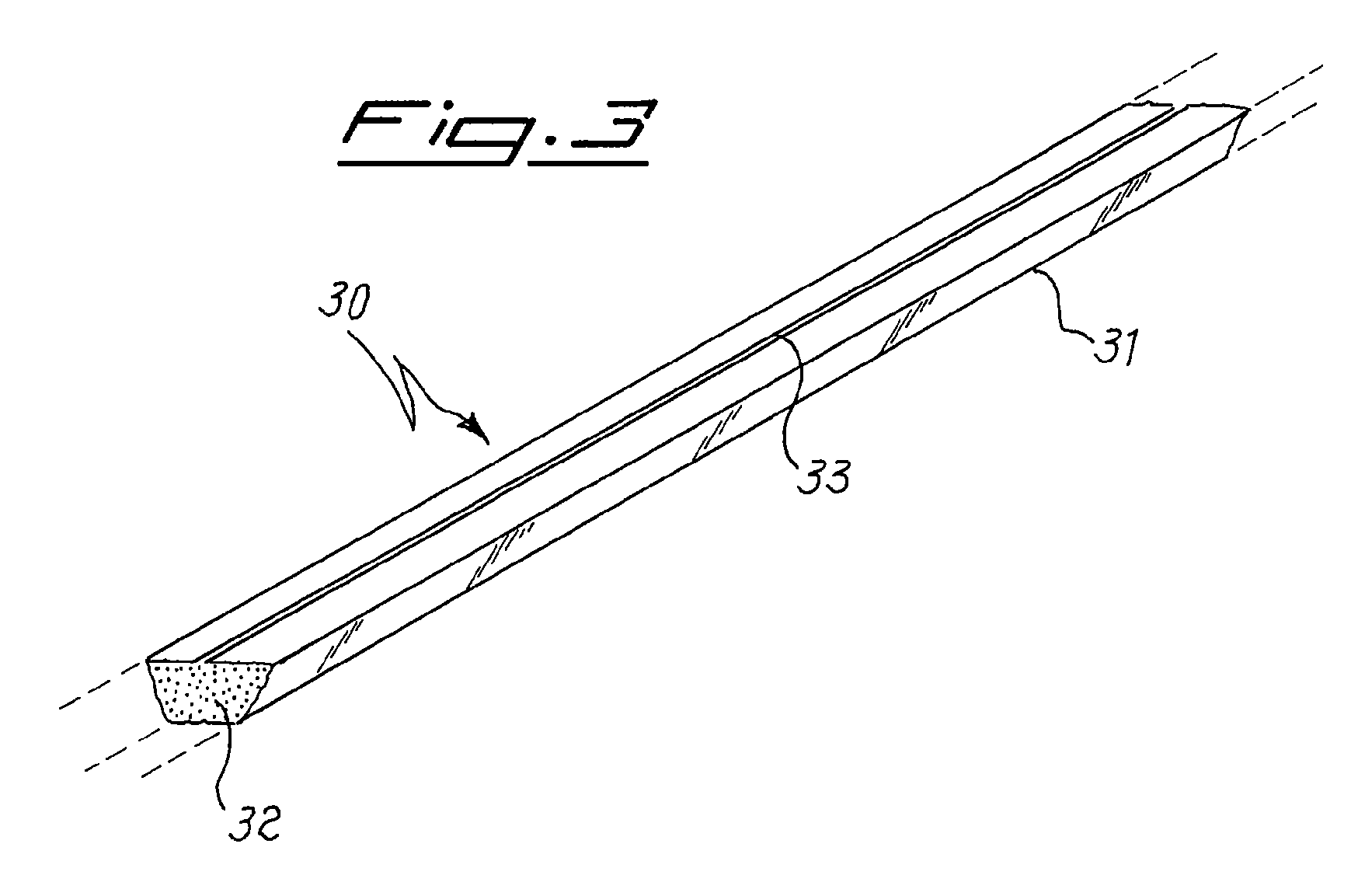
Image

Examples
example 1
[0046]This example relates to the preparation of a composition of the invention.
[0047]24.3 g of titanium foam, 70.9 g of copper powder and 4.8 g of tin powder are weighed. The three metals are placed in a crucible and then melted in an induction furnace under inert atmosphere. The produced ingot is milled and the powder is sieved, recovering the particle size fraction smaller than 125 μm. 7.5 g of this powder are mechanically mixed with 7.5 g of liquid mercury, and the mixture is sealed in a quartz vial under argon atmosphere. The vial is introduced into a sealed steel chamber which is airtight closed. This chamber is then inserted into a furnace, and heated up to 700° C. with the following thermal cycle:
[0048]ramp from room temperature to 500° C. in three hours;
[0049]holding at 500° C. for one hour;
[0050]ramp up to 600° C. in one hour;
[0051]holding at 600° C. for one hour;
[0052]ramp up to 700° C. in one hour;
[0053]holding at 700° C. for three hours;
[0054]natural cooling to room tem...
examples 2-5
[0062]These examples relate to the preparation of further compositions of the invention.
[0063]The procedure of Example 1 is repeated four times, starting with different ratios of the elements in the preparation of the alloy intended for reaction with mercury. The starting weights in grams of the elements employed in these four examples are given in Table 1.
[0064]
TABLE 1ExampleTiCuSnCrSi234.646.319.1 / / 348.231.919.9 / / 438.951.7 / 9.4 / 540.754.0 / / 5.3
[0065]After reaction with mercury, part of the powders produced in each example is analyzed by means of X-ray fluorescence; the measured compositions are reported in Table 2.
[0066]
TABLE 2ExampleTiCuSnCrSiHg222.830.612.6 / / 34.0333.722.313.9 / / 30.1422.429.7 / 5.4 / 42.5527.336.2 / / 3.633.0
example 6
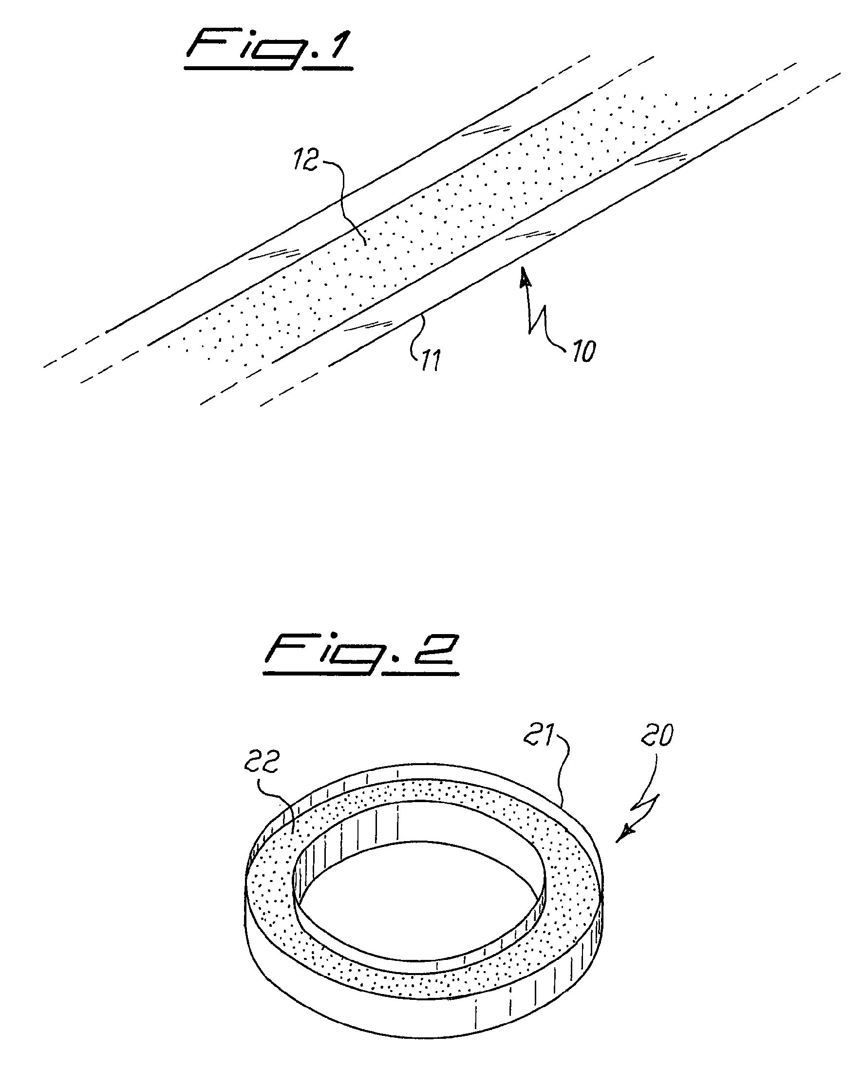
[0067]This example relates to a simulation of the sealing process of a lamp, to verify the mercury release under these conditions from the compositions produced in examples 1 to 5. Five devices of the type as shown in FIG. 2 are manufactured, by loading in the container 20 mg of the powders produced as the result of the procedure of examples 1 to 5. Each sample so prepared is introduced into a test chamber, the chamber is evacuated and maintained under pumping during the whole test, and the sample is inductively heated to 500° C. in 10 seconds and held at this temperature for 1 minute. From the weight difference before and after the test, the mercury emission from the sample at 500° C. is measured. It is found that for any of the five tested samples the amount of mercury released is less than 0.3% by weight (lower sensitivity limit of the measurement technique).
PUM
| Property | Measurement | Unit |
|---|---|---|
| particle size | aaaaa | aaaaa |
| temperature | aaaaa | aaaaa |
| temperature | aaaaa | aaaaa |
Abstract
Description
Claims
Application Information