Configurations and methods for removal of mercaptans from feed gases

a technology of mercaptan and feed gas, which is applied in the direction of gaseous fuels, machines/engines, combustible gas production, etc., can solve the problems of reducing the life of sulfur plants, overburdening process equipment, and conversion problems

Inactive Publication Date: 2010-03-09
FLUOR TECH CORP
View PDF16 Cites 17 Cited by
  • Summary
  • Abstract
  • Description
  • Claims
  • Application Information

AI Technical Summary

Problems solved by technology

Unfortunately, many gas streams also contain considerable quantities of non-acid gas contaminants, and particularly mercaptans and other sulfurous species (e.g. lower alkyl mercaptans, carbonyl sulfide, dimethyl disulfide, carbon disulfide, propanethiol, thiophene, etc.), which tend to participate in undesirable side reactions with the solvent.
While such processes generally satisfy sulfur removal requirements for various feed gases, several problems nevertheless remain.
For example, hydrotreating of the mercaptans laden liquids in an existing refinery unit may over-burden the process equipment, and will most often require modification of such equipment.
Also, the non-H2S sulfur-containing compounds in the gases to the sulfur plant will often create conversion problems in the sulfur plant.
Among other things, for high rates of thermal destruction of mercaptans and the organic sulfurs contaminants, the Claus reaction furnace needs to operate at a high flame temperature, which will significantly reduce the life of the sulfur plant and increase the capital and operating cost.
However, even with higher flame temperatures, thermal destruction of mercaptans is often incomplete.
Thus, co-absorption of CO2 by the solvent is often relatively high, which in turn necessitates higher solvent circulation and higher energy consumption.
Worse yet, co-absorption also leads to an acid gas rich in CO2, which is undesirable for downstream sulfur plants.
Thus, and especially where the feed gas comprises relatively large quantities of mercaptans and other organic sulfurs, capital and operating costs are significantly increased.
Additionally, other contaminants (e.g. unsaturated hydrocarbons, oxygen, and sulfur dioxide) may react with the solvent leading to degradation products and reduced solvent performance.
Unfortunately, most of such methods tend to be relatively inefficient and costly, and where contaminants are removed by a fixed bed absorbent process, they may further pose a disposal problem for the spent absorbent.
Therefore, various problems associated with operating efficiency, effluents, emissions, and product qualities, particularly in the downstream sulfur plant and tail gas unit, still remain.
For example, acid gas produced from such treating processes is generally poor in quality (e.g., comprising significant quantity of contaminants, and / or a relatively large quantity of co-absorbed CO2 and hydrocarbons), which often requires additional processing and higher energy consumption.
Furthermore, co-absorbed hydrocarbons in the acid gas must usually be converted to CO2 in the sulfur plant, which results in an increase in CO2 emissions from the process.
Thus, despite the significant potential energy value in the hydrocarbons, most of the currently known processes fail to recover these waste hydrocarbon streams as a valuable product.
Moreover, the contaminants and hydrocarbons in the acid gas of most known gas treatment configurations are often not completely destroyed in the sulfur plants, and the sulfur product will therefore be contaminated with unconverted hydrocarbons and mercaptans.
Therefore, while various gas processing treatments and configurations are known in the art, all or almost all of them suffer from one or more disadvantages, and especially where the feed gas comprises relatively high levels of acid gases, hydrocarbons, mercaptans, and organic sulfurs contaminants.

Method used


Image

  • Configurations and methods for removal of mercaptans from feed gases
  • Configurations and methods for removal of mercaptans from feed gases
  • Configurations and methods for removal of mercaptans from feed gases

Examples


Embodiment Construction

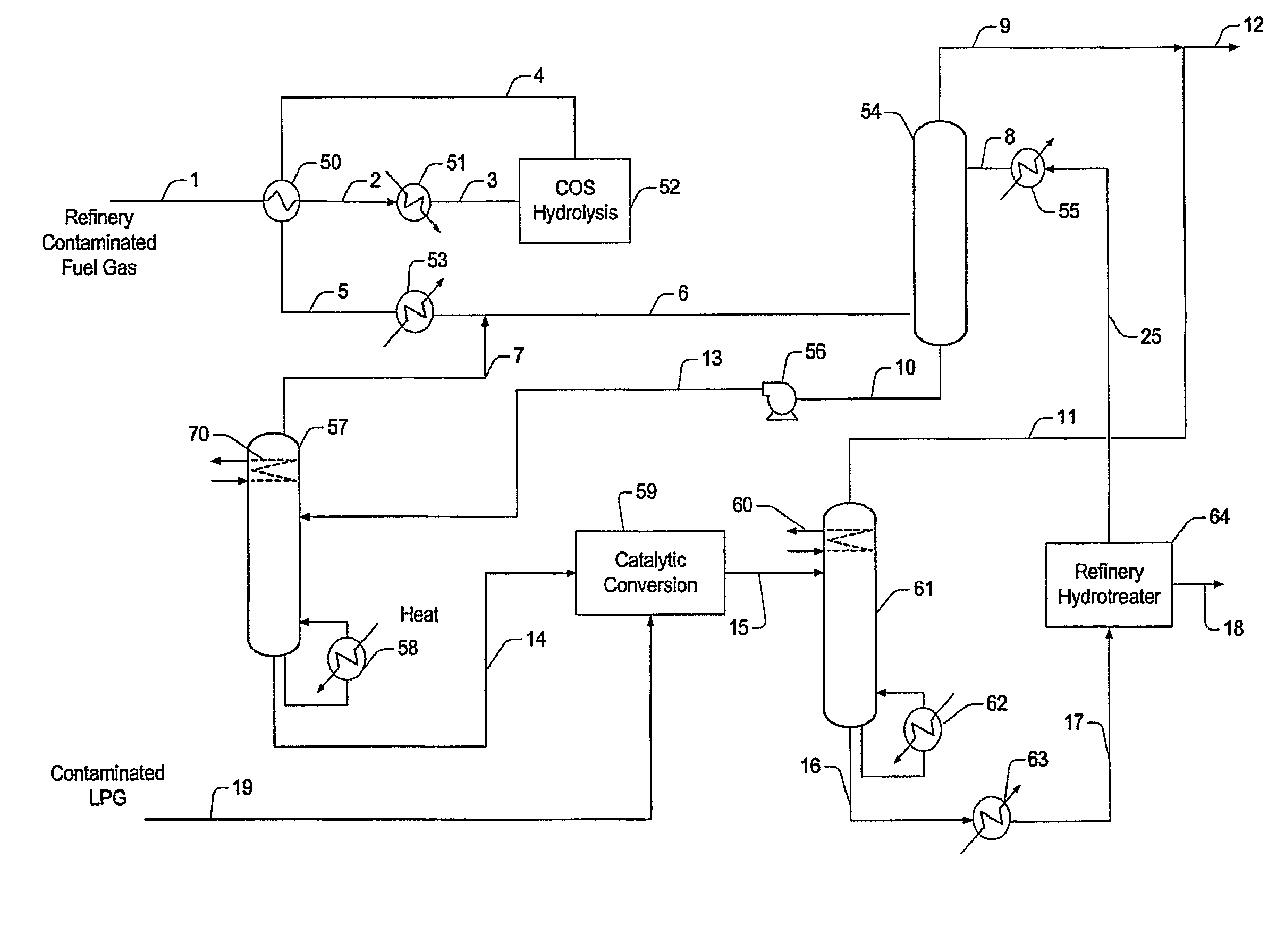
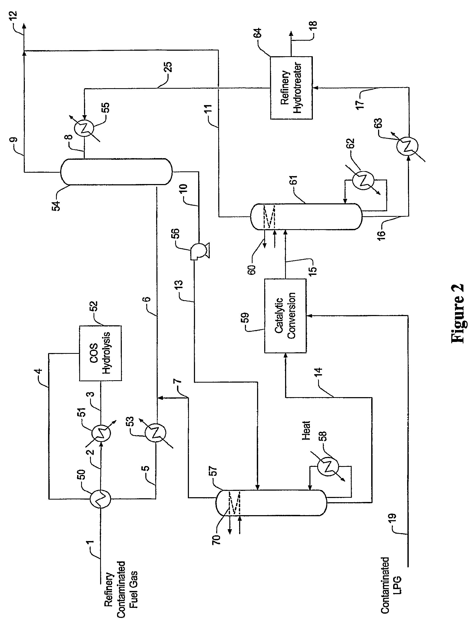
[0018]The present invention is directed to plant configurations and methods for treatment of a gas stream (e.g., refinery gas, fuel gas) comprising COS, acid gases, olefins, oxygen, heavy hydrocarbons, mercaptans (e.g., methyl, ethyl, propyl, butyl and heavier mercaptans), and / or organic sulfur contaminants, wherein the contaminants are first subjected to a COS hydrolysis stage, and wherein the so treated contaminants are then absorbed in an absorber that employs a solvent in which the H2S and the mercaptans are preferentially absorbed over light hydrocarbons (C1 to C4, inclusive). Light hydrocarbons carried over from the absorption step are removed from the solvent in a first distillation column and preferably fed back to the absorber. The rich solvent now containing the heavier hydrocarbons (C5+), H2S, and mercaptans is then subjected to an oxidative step to produce a disulfide-containing waste product, and remaining solvent with heavier components, which can then be processed in ...


PUM

PropertyMeasurementUnit
temperatureaaaaaaaaaa
corrosionaaaaaaaaaa

Abstract

A sulfur species-containing feed gas is processed in a treatment plant in which COS is hydrolyzed, and in which so produced hydrogen sulfide and other sulfur species are absorbed in a lean hydrocarbon liquid. The sulfur species in the so formed rich hydrocarbon liquid are then subjected to catalytic conversion into disulfides, which are subsequently removed from the rich solvent. Most preferably, sulfur free lean solvent is regenerated in a distillation column and / or refinery unit, and light components are recycled from the rich hydrocarbon liquid to the absorber.

Description

[0001]This application claims priority to our U.S. provisional patent application with the Ser. No. 60 / 764,513, which was filed Feb. 1, 2006.FIELD OF THE INVENTION[0002]The field of the invention is gas processing and treating, and especially gas processing and treating to remove sulfur-containing compounds from natural gas and refinery fuel gas.BACKGROUND OF THE INVENTION[0003]Gas streams can be treated in numerous manners to reduce acid gas content (e.g., H2S and / or CO2), typically using a solvent with more or less pronounced selectivity towards a specific acid gas component. Unfortunately, many gas streams also contain considerable quantities of non-acid gas contaminants, and particularly mercaptans and other sulfurous species (e.g. lower alkyl mercaptans, carbonyl sulfide, dimethyl disulfide, carbon disulfide, propanethiol, thiophene, etc.), which tend to participate in undesirable side reactions with the solvent. As a consequence of such reactions, solvent processing, replaceme...

Claims


Application Information

Patent Timeline
Patent Type & Authority Patents(United States)
IPC IPC(8): B01D53/48B01J19/00C07C319/24C10L3/08
CPCB01D53/1468B01D53/1493C10L3/102C10L3/12Y02C20/40
Inventor MAK, JOHN
Owner FLUOR TECH CORP
Why Eureka
Try Eureka