Fluid injection head, method of manufacturing the injection head, and fluid injection device

a technology of fluid injection and injection head, which is applied in the field of injection head, can solve the problems of ink ejecting characteristics gradually deteriorating, complex manufacturing process, and difficult high-density arrangement, and achieve the effect of preventing nozzle blockag

Inactive Publication Date: 2010-03-30
SEIKO EPSON CORP
View PDF17 Cites 10 Cited by
  • Summary
  • Abstract
  • Description
  • Claims
  • Application Information

AI Technical Summary

Benefits of technology

[0015]In light of the above-described circumstances, an object of the present invention is to provide a liquid jet head, a method of manufacturing the same, and a liquid jet apparatus, in which liquid ejecting characteristics can be kept constant for a long period and in which nozzle blockage is prevented.

Problems solved by technology

However, there is a problem that a manufacturing process is complex as follows: this type requires a difficult process of cutting a piezoelectric element into a comb-teeth shape while allowing the piezoelectric element to coincide with the array pitch of the nozzle orifices, and work of positioning and fixing the cut piezoelectric elements to the pressure generating chambers.
However, because of the utilization of flexure vibration, a certain area is required, and therefore there is a problem that high-density arrangement is difficult.
This causes changes in pressure to be given to the pressure generating chambers by the drive of piezoelectric elements, and therefore there is a problem that ink ejecting characteristics are gradually deteriorated.
However, since the nickel film or the like is also gradually dissolved by ink, there is a problem that ink ejecting characteristics are degraded after a long period of use.
In particular, when ink at a relatively high pH is used, the rate of solution is increased, and therefore ink ejecting characteristics are also degraded within a relatively short period.
Therefore, in a conventional ink-jet recording head, the resistance to ink in the reservoir portion has not been taken into consideration.
When the shape of the reservoir portion is greatly changed accordingly, a defect in the supply of ink to pressure generating chambers is caused and may lead to the degradation of ink ejecting characteristics.
The deposits are carried with the ink to the pressure generating chambers, and so-called nozzle blockage may be also caused.
Note that the above-described problems exist not only in an ink-jet recording head for ejecting ink but also similarly exist in other liquid jet head for jetting alkaline liquid other than ink, as a matter of course.

Method used


Image

  • Fluid injection head, method of manufacturing the injection head, and fluid injection device
  • Fluid injection head, method of manufacturing the injection head, and fluid injection device
  • Fluid injection head, method of manufacturing the injection head, and fluid injection device

Examples


embodiment 1

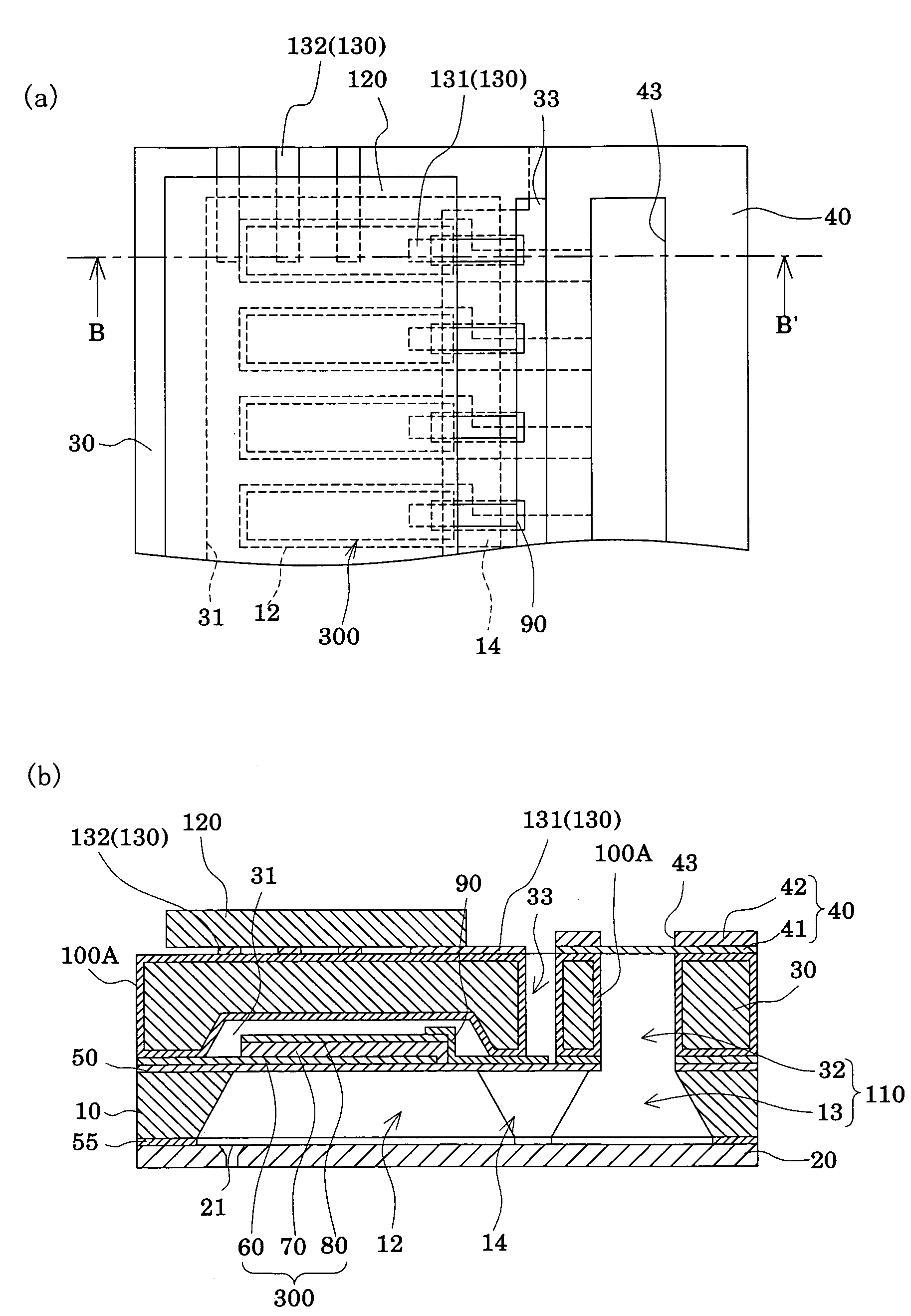
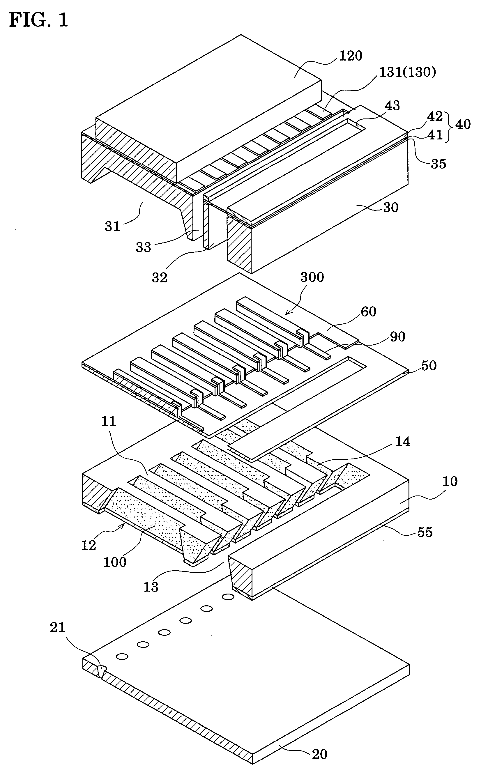
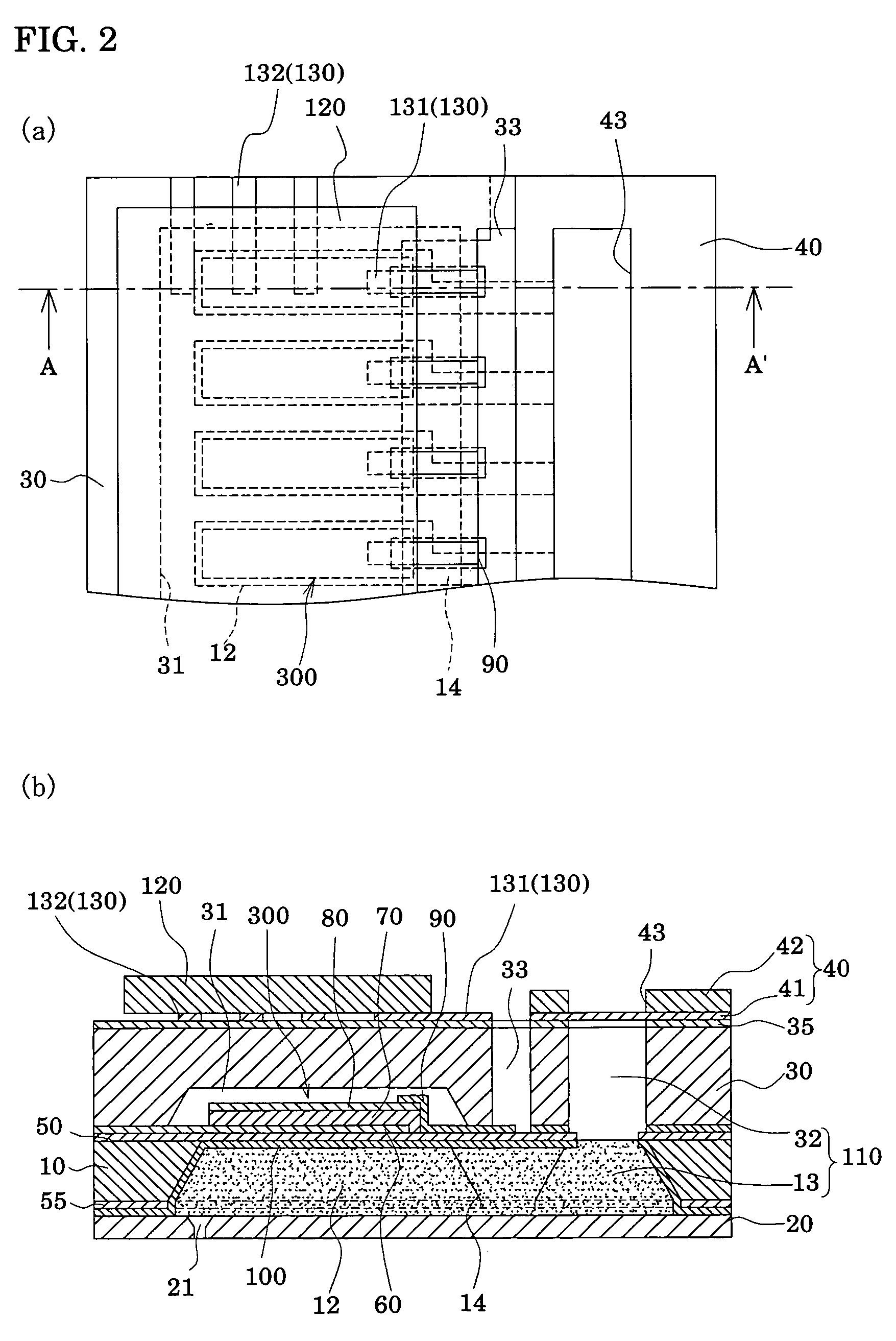
[0101]FIG. 1 is an exploded perspective view outlining an ink-jet recording head according to Embodiment 1 of the present invention. FIGS. 2(a) and 2(b) are a plan view and a sectional view of FIG. 1, respectively. As shown in these drawings, a passage-forming substrate 10 is made of a single crystal silicon substrate of plane orientation (110) in the present embodiment. An elastic film 50 and an insulation film 55, each having a thickness of 1 to 2 μm and made of silicon dioxide formed by thermal oxidation, are formed in advance on respective surfaces of the passage-forming substrate 10. In the passage-forming substrate 10, pressure generating chambers 12 which are divided into sections by a plurality of compartment walls 11 are arranged in parallel in the width direction thereof by performing anisotropic etching from one side of the passage-forming substrate 10. Moreover, on the outside of the pressure generating chambers 12 in the longitudinal direction thereof, a communicating p...

embodiment 2

[0133]FIGS. 9(a) and 9(b) are a plan view and a sectional view of an ink-jet recording head according to Embodiment 2, respectively. The present embodiment is an example in which a protective film having resistance to ink is provided at least on the inner wall surface of the reservoir portion 32 in the sealing plate 30. That is, as shown in FIGS. 9(a) and 9(b), in the present embodiment, an ink-resistant protective film 100A is provided on the entire surface of the sealing plate 30 including the inner wall surface of the reservoir portion 32, thus preventing the inner wall surface of the reservoir portion in the sealing plate 30 from being dissolved by ink. Moreover, the interconnections 130 are provided on the protective film 100A provided on the surface of the sealing plate 30 on the opposite side to the passage-forming substrate 10, and the drive IC 120 is mounted on the interconnections 130. That is, the protective film 100A on the surface of the sealing plate 30 serves as the a...

embodiment 3

[0141]FIGS. 11(a) and 11(b) are a plan view and a sectional view of an ink-jet recording head according to Embodiment 3, respectively. The present embodiment is another example of a protective film provided on the sealing plate. As shown in FIGS. 11(a) and 11(b), the present embodiment is the same as Embodiment 2 except that a protective film 100B, which is made of dielectric material and has resistance to ink (erosion resistance to ink), is formed on the inner wall surfaces of the piezoelectric element holding portion 31, of the reservoir portion 32, and of the penetrated hole 33 in the sealing plate 30, and on the joint surface of the sealing plate 30 with the passage-forming substrate 10 by physical vapor deposition (PVD) such as sputtering.

[0142]Also in such a structure, the sealing plate 30 can be prevented from being dissolved by ink, and the shape of the reservoir portion 32 can be maintained almost the same as when manufactured for a long period. Moreover, since the sealing ...


PUM

PropertyMeasurementUnit
pHaaaaaaaaaa
temperatureaaaaaaaaaa
thicknessaaaaaaaaaa

Abstract

Provided is a liquid jet head, a method of manufacturing the same, and a liquid jet apparatus, in which liquid ejecting characteristics can be kept constant for a long period and in which nozzle blockage is prevented. In a liquid jet head including a passage-forming substrate (10) which is made of a single crystal silicon substrate and in which pressure generating chambers (12) communicating with nozzle orifices are formed, and pressure generating elements (300) for causing pressure changes in the pressure generating chambers (12), a protective film (100) which is made of tantalum oxide and has resistance to liquid, is provided at least on the inner wall surfaces of the pressure generating chambers (12).

Description

TECHNICAL FIELD[0001]The present invention relates to a liquid jet head which ejects liquid to be jetted, a method of manufacturing the same, and a liquid jet apparatus. In particular, the present invention relates to an ink-jet recording head, a method of manufacturing the same, and an ink-jet recording apparatus, in which ink droplets are ejected from nozzle orifices by applying pressure, with piezoelectric elements, to ink supplied in pressure generating chambers communicating with the nozzle orifices for ejecting ink droplets.BACKGROUND ART[0002]Liquid jet apparatuses include, for example, an ink-jet recording apparatus equipped with an ink-jet recording head including a plurality of pressure generating chambers which generate pressure for ejecting ink droplets using piezoelectric elements or heater elements, a common reservoir which supplies the pressure generating chambers with ink, and nozzle orifices communicating with the respective pressure generating chambers. In the ink-...

Claims


Application Information

Patent Timeline
Patent Type & Authority Patents(United States)
IPC IPC(8): B41J2/135B41J2/045G01D15/00G11B5/127B41J2/055B41J2/14B41J2/16
CPCB41J2/14233B41J2/1606B41J2/161B41J2/1623B41J2/1629B41J2/1631B41J2/1632B41J2/1635B41J2/1642B41J2/1646B41J2002/14241B41J2002/14419B41J2002/14491
Inventor YASOSHIMA, TAKESHISHIMADA, MASATOMATSUZAWA, AKIRA
Owner SEIKO EPSON CORP
Why Eureka
Try Eureka