
Method and apparatus for measuring on-line failure of turbine thermal barrier coatings

a technology of turbine thermal barrier coating and online failure, which is applied in the direction of heat measurement, optical radiation measurement, instruments, etc., can solve the problems of system failure, requiring expensive repairs, and exposing the superalloy component to degradation or failure, so as to avoid severe repair and maintenance costs, accelerate the sale of advanced power plants, and remain competitive in the global market

Inactive Publication Date: 2010-04-06
SIEMENS ENERGY INC
View PDF73 Cites 63 Cited by
  • Summary
  • Abstract
  • Description
  • Claims
  • Application Information

AI Technical Summary

Benefits of technology

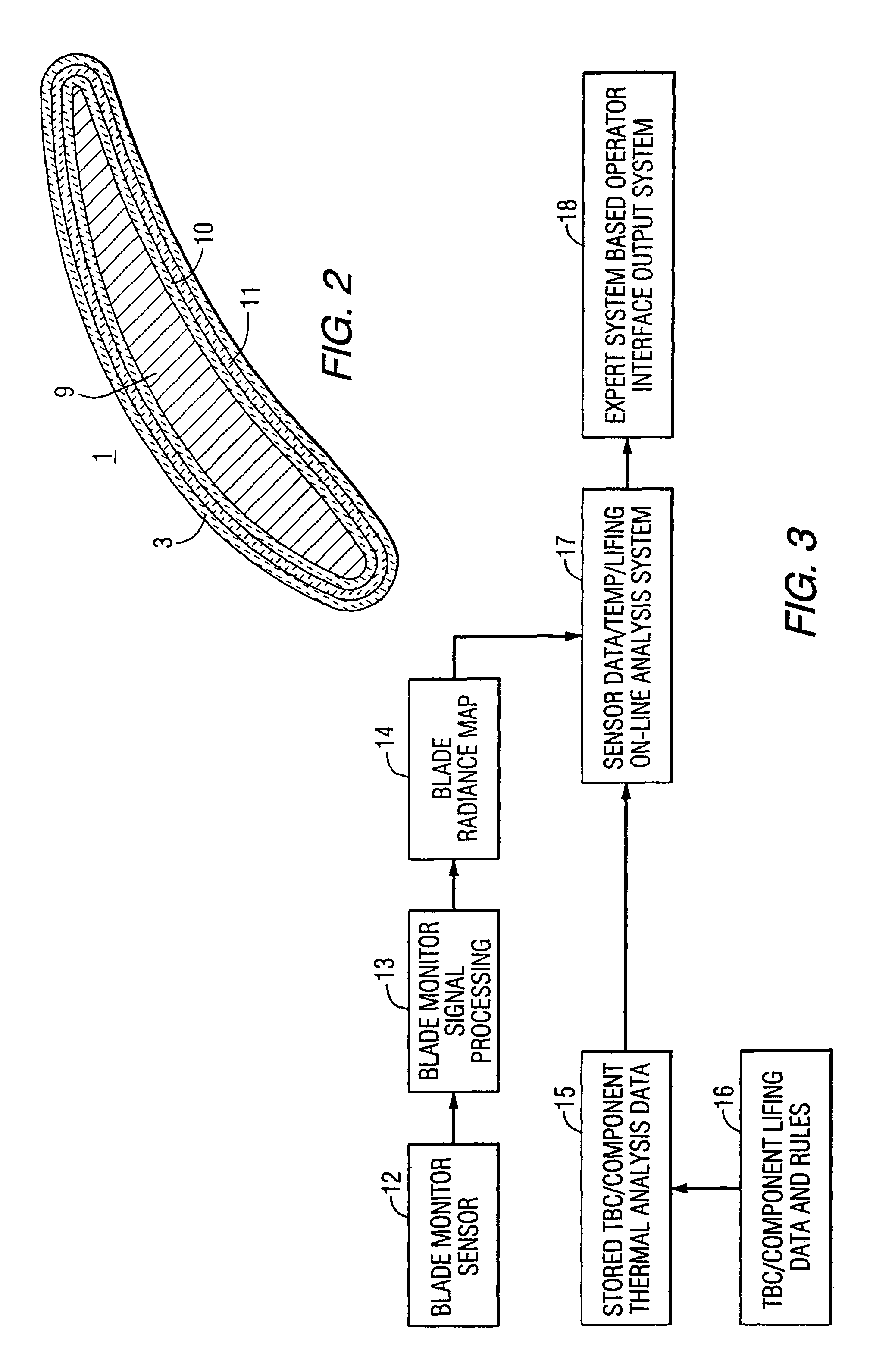
"The present invention provides a method and apparatus for monitoring the health of ceramic components in high-temperature turbine engines. The method involves using infrared thermal imaging to monitor for delamination or other damage to the components, and a database to analyze the data and make recommendations for repair or maintenance. The system can detect and evaluate potential failures quickly, allowing for timely repairs or adjustments to the operating parameters of the turbine. The invention can help improve the reliability and efficiency of advanced turbine engines, and lower the cost of electricity by accelerating the sale of advanced power plants and improving plant efficiency through advanced upgrade packages."

Problems solved by technology

Long term exposure of these ceramic coatings to the hostile, high temperature, abrasive environment in which such turbines operate can cause phase destabilization, sintering, microcracking, delamination and ultimately spallation within the coating layers, exposing the superalloy component to degradation or failure and requiring expensive repairs.
However, this system requires failure to occur, for example by melting of components and detection of ions.

Method used


Image

  • Method and apparatus for measuring on-line failure of turbine thermal barrier coatings
  • Method and apparatus for measuring on-line failure of turbine thermal barrier coatings
  • Method and apparatus for measuring on-line failure of turbine thermal barrier coatings

Examples


Embodiment Construction

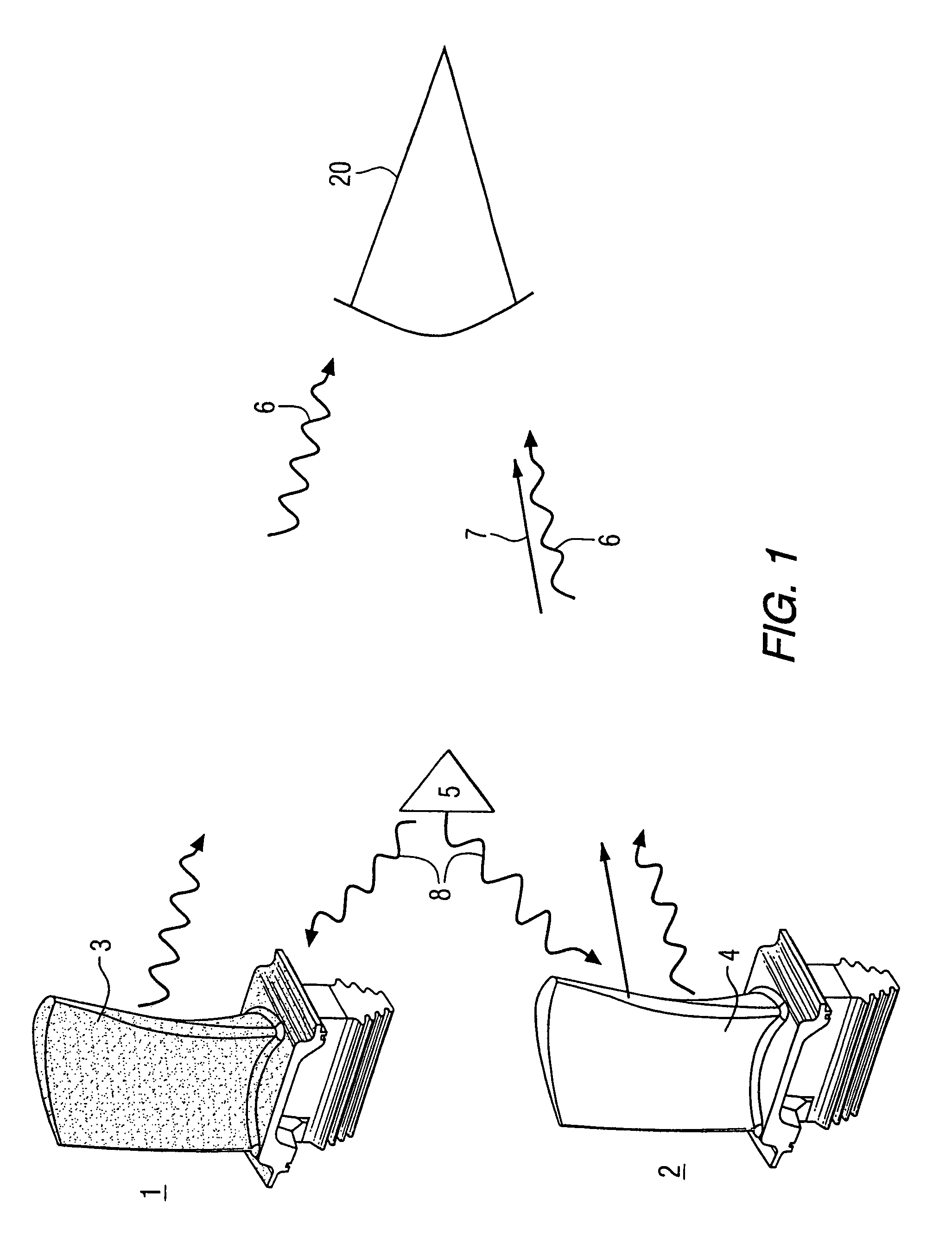
[0024]Aspects of this invention will provide a means of examining TBC coatings at various stages during the life cycle of the component. In the on-line system, this invention would allow notification within several seconds of debonding and spallation and cooling system failure during the uninterrupted operation of the turbine engine. Furthermore, by tracking the surface temperature in time, long term degradation mechanisms, such as erosion and sintering can be evaluated. This is of key importance with new engine designs where eminent engine failure could occur within minutes of a coating failure.

[0025]In one exemplary embodiment, a system embodying aspects of the present invention will be configured to measure the radiance of a moving turbine blade in a gas turbine under operating conditions. The blades may be moving at supersonic linear speeds in the order of approximately Mach 1.2 or 890 miles per hour. Surface temperature of the TBC for a turbine blade under normal operating cond...


PUM

PropertyMeasurementUnit
wavelengthsaaaaaaaaaa
integration timeaaaaaaaaaa
linear speedsaaaaaaaaaa

Abstract

A method of remotely monitoring the radiant energy (6) emitted from a turbine component such as a turbine blade (1) having a low-reflective surface coating (3) which may be undergoing potential degradation is used to determine whether erosion, spallation, delamination, or the like, of the coating (3) is occurring.

Description

[0001]This application is a Continuation-In-Part of U.S. application Ser. No. 09 / 470,123 filed Dec. 22, 1999 now abandoned.GOVERNMENT CONTRACT[0002]The Government of the United States of America has rights in this invention pursuant to Contract DE-AC05-950R22242 awarded by the United States Department of Energy.BACKGROUND OF THE INVENTION[0003]1. Field of the Invention[0004]The invention relates to means to identify, monitor and take action upon potential delamination of ceramic coatings used as a thermal barrier for turbine components.[0005]2. Background Information[0006]Cobalt or nickel based superalloys of, for example, IN738, or ECV768 are used for making blades, vanes and other components of gas turbines. These turbines can operate at temperatures in the range of 1000 C. to 1600 C. and are generally protected by a series of protective coatings. The coatings usually comprise layers of metallic base coats, service formed aluminum oxide layers and a final ceramic thermal barrier c...

Claims


Application Information

Patent Timeline
Patent Type & Authority Patents(United States)
IPC IPC(8): G01N25/72G01J5/00G01K13/00G01N17/00F01D5/28F01D21/00F01D21/12F01D21/14
CPCF01D5/288F01D21/003F01D21/12F01D21/14G01J5/0022G01N25/72F05D2270/303Y02T50/67F05D2300/611F05D2230/90F05D2270/11Y02T50/60
Inventor ZOMBO, PAUL J.LEMIEUX, DENNISDIATZIKIS, EVANGELOS
Owner SIEMENS ENERGY INC
Learn More