Embolectomy catheters and methods for treating stroke and other small vessel thromboembolic disorders

a technology of thromboembolic disorders and emboli, which is applied in the field of thromboembolic catheters, can solve the problems of tissue ischemia, lack of available oxygen and nutrients for the tissue, and normal flow of arterial blood, so as to prevent or minimize the severity of stroke

Inactive Publication Date: 2010-04-06
MICROVENTION INC
View PDF48 Cites 145 Cited by
  • Summary
  • Abstract
  • Description
  • Claims
  • Application Information

AI Technical Summary

Benefits of technology

[0016]The present invention generally comprises an embolectomy catheter device and method for removing blood clots or other matter from the lumens of blood vessels or other anatomical conduits of a mammalian body. The embolectomy catheters and methods of the present invention are particularly suitable for use in removing clots or thromboemboli from small arteries of the mammalian brain to prevent or minimize the severity of stroke.
[0024]A further embolectomy catheter device of the present invention generally comprises; a) an elongate, pliable clot penetrating catheter which is advanceable, distal end first, through the clot or other obstructive matter (e.g., thrombus, thromboembolus, pieces of detached atherosclerotic plaque, foreign matter, etc.) which is to be removed, and b) a matter capturing receptacle which is deployable from the distal end of the catheter after it has been advanced through the obstructive matter, to capture and facilitate removal of the obstructive matter. The matter capturing receptacle is initially disposed in a first or stowed configuration wherein the receptacle is in a radially collapsed condition and contained upon or within the catheter or otherwise sufficiently compact to pass through the clot or other obstructive matter. Thereafter, the matter capturing receptacle is deployable (e.g., advanceable, projectable and / or expandable) from the catheter such that it assumes a second or expanded configuration wherein the receptacle may receive and at least partially surround the distal aspect of the clot or other obstructive matter so as to facilitate extraction and removal of the blood clot or other obstructive matter along with the catheter.
[0025]A guidewire lumen may extend longitudinally through the entire length of the catheter (i.e., an “over-the-wire” embodiment) or through only a distal portion of the catheter (i.e., a “rapid exchange” embodiment). In either of these embodiments of the catheter, the guidewire lumen may extend through the matter capturing receptacle such that the catheter (with its matter capturing receptacle in its collapsed or stowed configuration) may be advanced over a guidewire which has previously been passed through the vessel-obstructing clot or other obstructive matter. Such arrangement of the guidewire lumen additionally allows the embolectomy catheter to be exchanged (e.g., removed and replaced with another embolectomy catheter or another type of catheter) if such exchange should become necessary or desirable. This ability to allow the guidewire to remain positioned through the offending clot or other obstructive matter may serve to ensure that the catheter or its replacement can be re-advanced through the clot or other obstructive matter to its desired position.
[0029]Further in accordance with the present invention, there is provided a rapid exchange microcatheter which comprises a small diameter flexible microcatheter of a type commonly used in neuroradiology procedures (e.g., Prowler™ microcatheter, Cordis Endovascular Systems, Miami Lakes, Fla.), which has greater flexibility at or near its distal end than at or near its proximal end, and which includes in accordance with this invention, the addition of a guidewire passage port formed in the sidewall of the catheter, at a spaced distance (e.g., 0.5-35 cm) from its distal tip. A guidewire deflector may be formed within the main lumen of the catheter adjacent to the guidewire passage aperture, to deflect the proximal end of a guidewire out of the guidewire passage aperture as the catheter is advanced over the guidewire. The formation of such guidewire passage aperture and guidewire deflector allows a guidewire to be passed through only a distal portion of the catheter lumen. This lumen arrangement allows the microcatheter to be exchanged (i.e., removed and replaced by another microcatheter or an embolectomy catheter of the above-summarized design) while the operator holds the guidewire in place by grasping the exteriorized proximal end of the guidewire—even in instances where a standard length guidewire (i.e., not an “exchange-length” guidewire) is used.
[0038]E. withdrawing and removing the microcatheter while substantially maintaining the small guidewire in its operative position (e.g., preventing the guidewire from moving so far as to lose the access to the obstructive matter that the presence of the guidewire provides);

Problems solved by technology

Moreover, peripheral venous embolisms may migrate to other areas of the body where even more serious untoward effects can result.
In cases where the thromboembolus is located within an artery, the normal flow of arterial blood may be blocked or disrupted, and tissue ischemia (lack of available oxygen and nutrients required by the tissue) may develop.
In such cases, if the thromboembolism is not relieved, the ischemic tissue may become infarcted (i.e., necrotic).
Depending on the type and location of the arterial thromboembolus, such tissue infarction can result in death and amputation of a limb, myocardial infarction, or stroke.
Notably, strokes caused by thromboemboli which become lodged in the small blood vessels of the brain continue to be a leading cause of death and disability, throughout the world.
However, the thrombolytic and / or anticoagulant drugs used in these pharmacologic treatments can cause untoward side effects such as bleeding or hemorrhage.
Also, in cases where time is of the essence, such as cases where an arterial thromboembolism is causing severe tissue ischemia (e.g., an evolving stroke or an evolving myocardial infarction) the time which may be required for the thrombolytic drugs to fully lyse or dissolve the blood clot and restore arterial blood flow may be too long to avoid or minimize the impending infarction.
Open surgical thrombus-removing procedures can, in many cases, be used to rapidly remove clots from the lumens of blood vessels, but such open surgical procedures are notoriously invasive, often require general anesthesia, and the use of such open surgical procedures is generally limited to blood vessels which are located in surgically accessible areas of the body.
For example, many patients suffer strokes due to the lodging of blood clots in small arteries located in surgically inaccessible areas of their brains and, thus, are not candidates for open surgical treatment.
However, such catheter-based interventional procedures are highly operator-skill-dependent, and can be difficult or impossible to perform in small or tortuous blood vessels.
Thus, patients who suffer strokes due to the presence of clots in the small, tortuous arteries of their brains may not presently be candidates for catheter-based, transluminal removal of the clot, due to the small size and tortuosity of the arteries in which their clots are located.
However, none of the prior art trasluminally deployable clot capturing type of catheters are believed to be of optimal design for use in the small blood vessels of the brain because they are a) not equipped with appropriate guidewire passage lumens to allow them to be passed over previously inserted, small-diameter (e.g., 0.006-0.018 inch) guidewires, b) they are not adapted for rapid exchange over a guidewire of standard length (e.g., a guidewire which is less than twice the length of the catheter) and c) the clot capturing receptacles of these catheters are not optimally constructed and configured for removal of clots from very small blood vessels as are typically found in the brain.
Despite extensive development in this area, for the reasons stated above and / or other reasons, none of the prior art embolectomy catheters are believed to be optimally designed for treating ischemic stroke.

Method used


Image

  • Embolectomy catheters and methods for treating stroke and other small vessel thromboembolic disorders
  • Embolectomy catheters and methods for treating stroke and other small vessel thromboembolic disorders
  • Embolectomy catheters and methods for treating stroke and other small vessel thromboembolic disorders

Examples


first embodiment

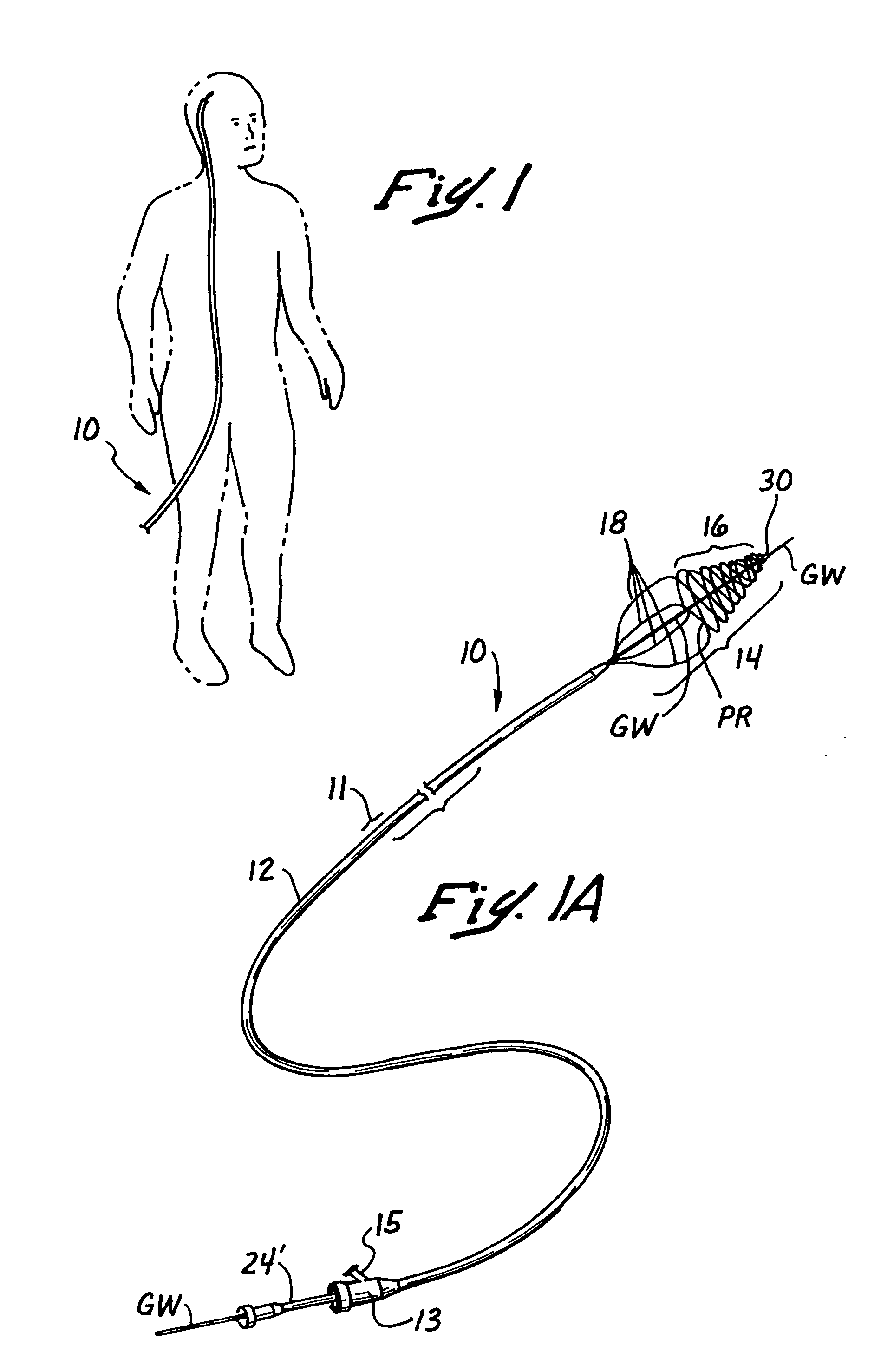
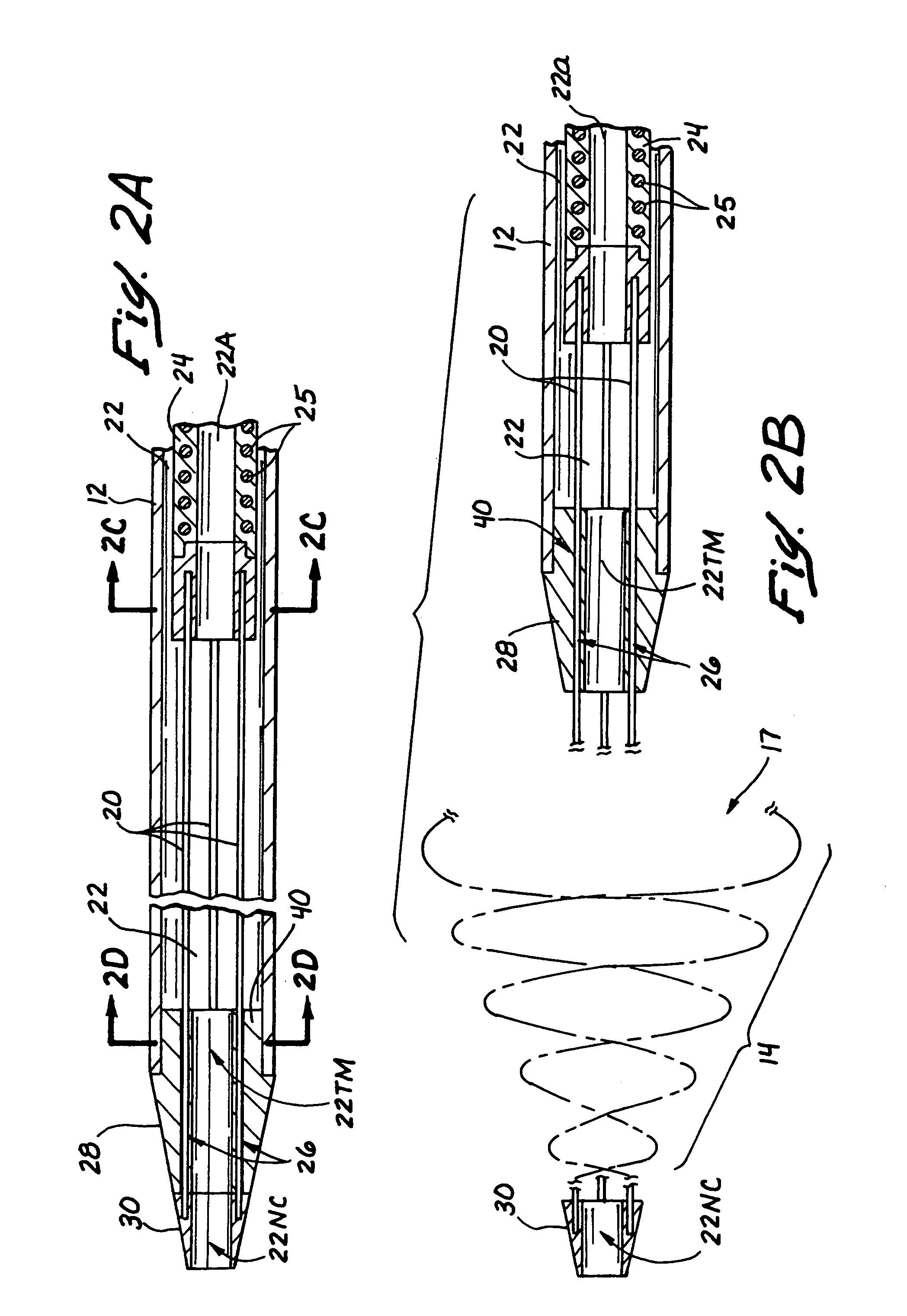
[0116]As shown in FIGS. 1-2D, the first embodiment of the over-the-wire catheter device10 comprises an elongate, pliable catheter 11 having a clot capturing receptacle 14 deployable from its distal end DE, as shown. The obstructive matter-capturing receptacle 14 is formed of a plurality (e.g., 2 or more) wire members 20 which are initially retractable to substantially straight configurations and a first (i.e., stowed) position, within the catheter 11. (See FIG. 2A) When it is desired to deploy the obstructive matter capturing receptacle 14, the preformed wire members 20 are held stationary while the catheter 11 is retracted, or the wire members 20 are advanced in the distal direction while holding the catheter 11 stationary, such that the wires emerge from the constraint of the catheter 11 and resiliently assume a second (i.e. operative) configuration wherein the distal portions of the wire members form a helical basket 16 having an open proximal mouth or rim 17, as shown in FIG. 2B...

second embodiment

[0121]FIGS. 3B and 3B′ show a second embodiment of an over-the-wire catheter device 10′ which differs from the first embodiment 10 in several ways. For example, the obstructive matter-capturing receptacle (not shown) of this second embodiment is formed by only two (2) wire members 20′ instead of four (4) as in the first embodiment 10. Also, the catheter 11′ of this second embodiment incorporates an elongate distal segment 270 of reduced diameter and increased flexibility—similar to that of the commercially available microcatheters (e.g., Prowler™ microcatheter, Cordis Endovascular Systems, Miami Lakes, Fla.), an example of which is shown in FIG. 3A and generally comprises a proximal portion PP having a lumen L and a distal segment 270 having a lumen 271 which is continuous with the lumen L of the proximal portion PP.

[0122]With specific reference to FIGS. 3B and 3B′, this second embodiment of the over the wire embolectomy catheter device 10′ comprises an elongate, pliable catheter 11...

third embodiment

[0125]FIGS. 3D and 3D′ show a third embodiment (i.e., a rapid exchange type embodiment) of the embolectomy catheter device 10″ which is similar in construction to the above described second embodiment 10′, but which incorporates a guidewire passage port 267′ formed in the sidewall of the catheter 11″ near the distal end of its proximal portion 12′, and a guidewire deflector tube 260′ which extends from the guidewire passage port 267′ to the lumen 22′. The guidewire deflector tube 260′ has a flared distal end which is held in a centered position within the lumen by a plurality of radial support members 264′. Longitudinal passages 266,266(alt) are formed between the radial support members 264′ to allow radiographic contrast medium or other fluid to flow through the lumen 22′, past the flared distal end of the guidewire deflector tube 260′. Selected ones of the longitudinal passages 266(alt) are larger than the others 266 to permit the elongate members 20′ which form the obstructive ma...


PUM


Abstract

Embolectomy catheters, rapid exchange microcatheters, systems and methods for removing clots or other obstructive matter (e.g., thrombus, thromboemboli, embolic fragments of atherosclerotic plaque, foreign objects, etc.) from blood vessels. This invention is particularly useable for percutaneous removal of thromboemboli or other obstructive matter from small blood vessels of the brain, during an evolving stroke or period of cerebral ischemia. In some embodiments, the embolectomy catheters of this invention are advanceable with or over a guidewire which has been pre-inserted through or around the clot. Also, in some embodiments, the embolectomy catheters include clot removal devices which are deployable from the catheter after the catheter has been advanced at least partially through the clot. The clot removal device may included a deployable wire nest that is designed to prevent a blood clot from passing therethrough. The delivery catheter may include telescoping inner and outer tubes, with the clot removal device being radially constrained by the outer tube. Retraction of the outer tube removes the constraint on the clot removal device and permits it to expand to its deployed configuration. An infusion guidewire is particularly useful in conjunction with the embolectomy catheter, and permits infusion of medicaments or visualization fluids distal to the clot.

Description

[0001]This is a continuation of application Ser. No. 09 / 437,530 filed Nov. 10, 1999 now U.S. Pat. No. 6,685,722 which is a continuation-in-part of application of Ser. No. 09 / 071,561 filed on May 1, 1998 and now issued as U.S. Pat. No. 6,511,492 on Jan. 28, 2003FIELD OF THE INVENTION[0002]The present invention relates generally to medical methods and devices, and more particularly to thrombolectomy catheters, and methods for using such catheters, for removing blood clots or other matter from the lumens of blood vessels or other anatomical conduits.BACKGROUND OF THE INVENTION[0003]Various types of thromboembolic disorders, such as stroke, pulmonary embolism, peripheral thrombosis, atherosclerosis, and the like, are known to occur in human beings and other mammals. Such thromboembolic disorders are typically characterized by the presence of a thromboembolus (i.e., a viscoelastic blood clot comprised of platelets, fibrinogen and other clotting proteins) which has become lodged at a spec...

Claims


Application Information

Patent Timeline
Patent Type & Authority Patents(United States)
IPC IPC(8): A61M29/00A61B17/221A61B17/22A61F2/958
CPCA61B17/221A61F2/013A61B17/22032A61B17/135A61M2025/0042A61B2017/22034A61B2017/22044A61B2017/22077A61B2017/22084A61B2017/22094A61B2017/2212A61B2017/320716A61M2025/0183A61F2002/016A61F2002/018A61F2230/008A61F2230/0091
Inventor ROSENBLUTH, ROBERT F.GREEN, JR., GEORGE R.COXSTERNWEILER, THOMAS R.CHOW, SEAN L.MONETTI, RICHARD R.
Owner MICROVENTION INC
Why Eureka
Try Eureka