
Aerosol gels

a gel and aerosol technology, applied in the field of aerosol gels, can solve the problems of low overall thermal conductivity of all, low solid thermal conductivity, and low gaseous conductivity,

Active Publication Date: 2010-04-06
KANSAS STATE UNIV RES FOUND
View PDF19 Cites 7 Cited by
  • Summary
  • Abstract
  • Description
  • Claims
  • Application Information

AI Technical Summary

Benefits of technology

This method produces gels with unprecedented low densities and high surface areas, eliminating the need for supercritical drying and enabling their use in various applications like insulation, electrodes, and thermal management without damaging the gel structure.

Problems solved by technology

The extremely low overall thermal conductivities of all aerogel materials is due partly to their high pore contents causing their solid thermal conductivities to be very low.
On the other hand, the very small sizes of their pores cause their gaseous conductivities to also be quite low.

Method used


Image

  • Aerosol gels
  • Aerosol gels
  • Aerosol gels

Examples


example 1

[0044]A series of carbon gels were produced using a 17-liter closed combustion chamber. In each instance, an explosive mixture of liquid or gaseous hydrocarbon and oxygen (e.g., 2 parts acetylene by volume / 1 part oxygen by volume) were introduced into the chamber at up to 1 atmosphere pressure at room temperature. The gaseous hydrocarbons were injected as a gas, whereas the liquid hydrocarbons were injected as a liquid aerosol (oxygen) mist having an average particle size estimated to be on the order of 1 micron.

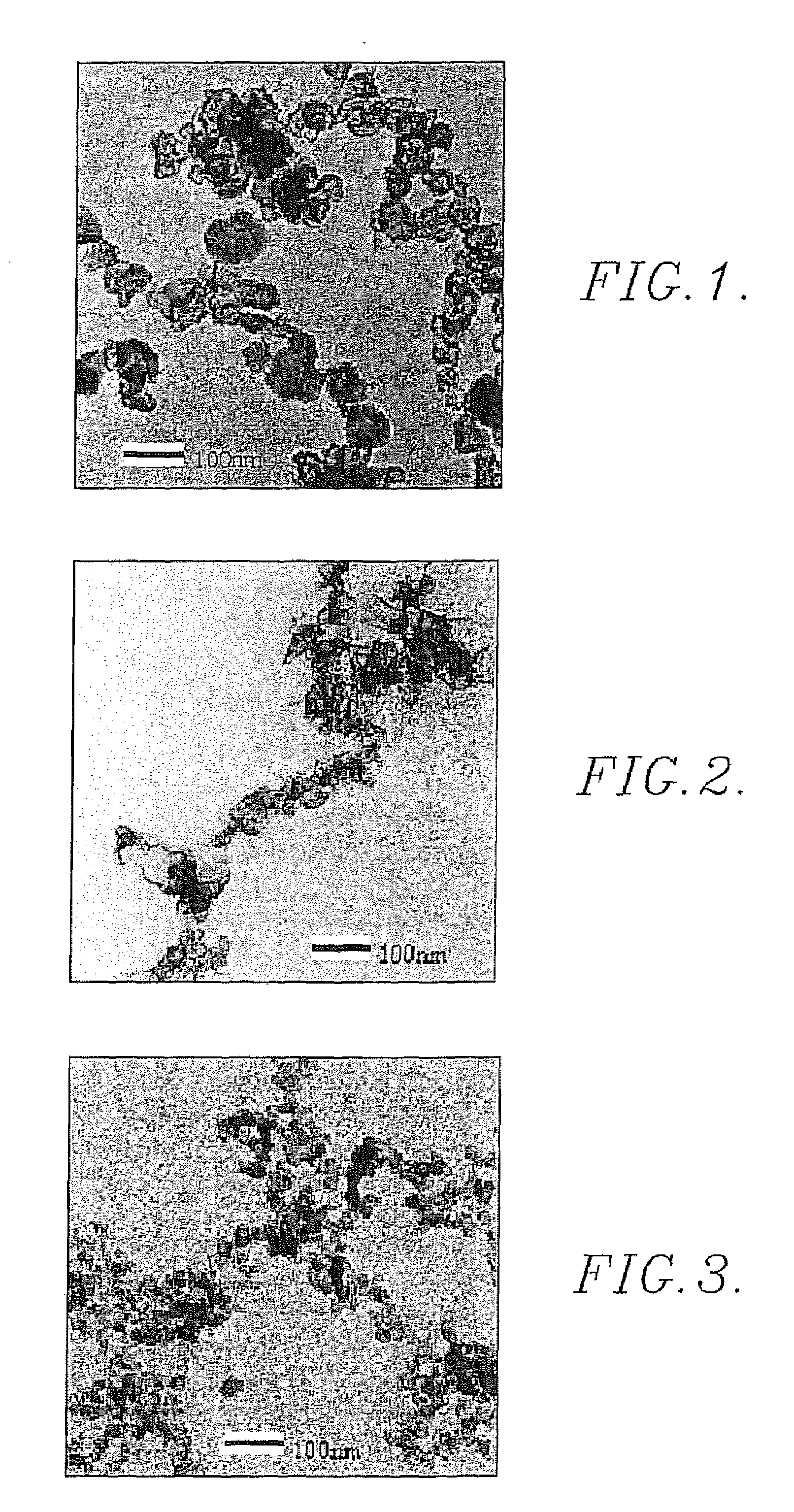
[0045]A conventional spark plug having its electrode within the chamber was used to ignite the mixture; the spark was generated using a Tesla coil coupled to the spark plug. Generation of the spark caused an instantaneous explosion which rapidly produced nanometer-sized (up to about 50 nm) carbon particles, which quickly aggregated to form ramified fractal carbon structures. After the explosion, the material within the chamber was allowed to sit quiescently for a period of a...

example 2

[0060]Silica (SiO2) aerosol gels were prepared by spontaneous explosive reaction of silane (SiH4) with either oxygen (O2) or nitrous oxide (N2O). These reactions were performed in the presence of an inert background gas such as nitrogen (N2) or carbon dioxide (CO2), but otherwise the procedure used was the same as that set forth in Example 1 for the preparation of carbon aerosol gels. It is believed that the silica nanoparticles are in a molten state when they are formed, and therefore without inert background gas these nanoparticles will move balistically and “splash” on the chamber walls. Thus, the role of the inert background gas is to help in quickly quenching the fresh silica nanoparticles below the melting temperature thereof and before they collide with the chamber walls or each other. Typically, 0.46 moles of background gas was used in the 3.9 liter explosion chamber, About 0.016 moles of silane and 1.4 times the stoichiometric amount of oxygen was used in each reaction. Ass...


PUM

PropertyMeasurementUnit
average radiusaaaaaaaaaa
radiusaaaaaaaaaa
densityaaaaaaaaaa

Abstract

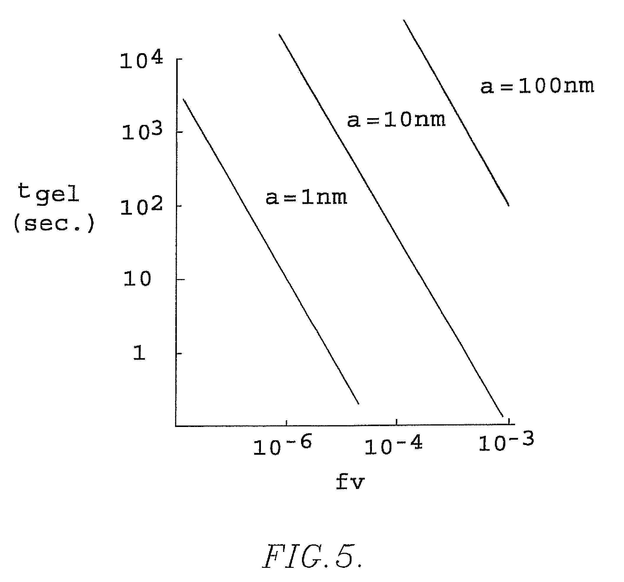
An improved process for the production of ultralow density, high specific surface area gel products is provided which comprises providing, in an enclosed chamber, a mixture made up of small particles of material suspended in gas; the particles are then caused to aggregate in the chamber to form ramified fractal aggregate gels. The particles should have a radius (a) of up to about 50 nm and the aerosol should have a volume fraction (fv) of at least 10−4. In preferred practice, the mixture is created by a spark-induced explosion of a precursor material (e.g., a hydrocarbon) and oxygen within the chamber. New compositions of matter are disclosed having densities below 3.0 mg / cc.

Description

CROSS-REFERENCE TO RELATED APPLICATION[0001]This application is a continuation-in-part of International Application PCT / US2005 / 033832, filed Sep. 20, 2005, which claims the benefit of Provisional Application Ser. No. 60 / 613,027, filed Sep. 24, 2004. All of the foregoing applications are incorporated by reference herein.FEDERALLY SPONSORED RESEARCH / DEVELOPMENT PROGRAM[0002]This invention was made with government support under NSF Grant No. CTS0080017 and NASA Grant No. 3-2360 awarded by the United States Army Research Office. The government has certain rights in the invention.BACKGROUND OF THE INVENTION[0003]1. Field of the Invention[0004]The present invention is broadly concerned with new processes for the formation of low-density, high surface area gel products. More particularly, the invention is directed to such methods and the novel gel products themselves, wherein the gel products are formed in an enclosed chamber containing a mixture including particles of material suspended i...

Claims


Application Information

Patent Timeline
Patent Type & Authority Patents(United States)
IPC IPC(8): B01F3/06B01F23/30
CPCB01J13/0095C01B31/00C09K3/30C01G23/053C01B33/16Y10S516/922Y10S516/924C01B32/00
Inventor SORENSEN, CHRISTOPHER M.CHAKRABARTI, AMITABHADHAUBHADEL, RAJANGERVING, COREY
Owner KANSAS STATE UNIV RES FOUND
Learn More