
Method based on backboard transmitting time division multiplexing circuit data and a bridge connector

a time division multiplexing circuit and data transmission technology, applied in time division multiplexing selection, electrical equipment, selection arrangements, etc., can solve the problems of signal distortion, system reliability is greatly reduced, system capacity cannot be further increased, etc., to reduce noise interference and emi, reduce transmission clock phase accuracy, and increase transmission rate and switching capacity on the backplane

Inactive Publication Date: 2010-04-13
HUAWEI TECH CO LTD
View PDF20 Cites 2 Cited by
  • Summary
  • Abstract
  • Description
  • Claims
  • Application Information

AI Technical Summary

Benefits of technology

[0011]Considering what have been mentioned above, the invention provides a method for multi-path TDM data transmission based on backplane and a bridge connector thereof in order to reduce synchronization requirement of the clock, increase transmission rate at the backplane circuit and switching capacity, and raise data transmission quality and reliability.
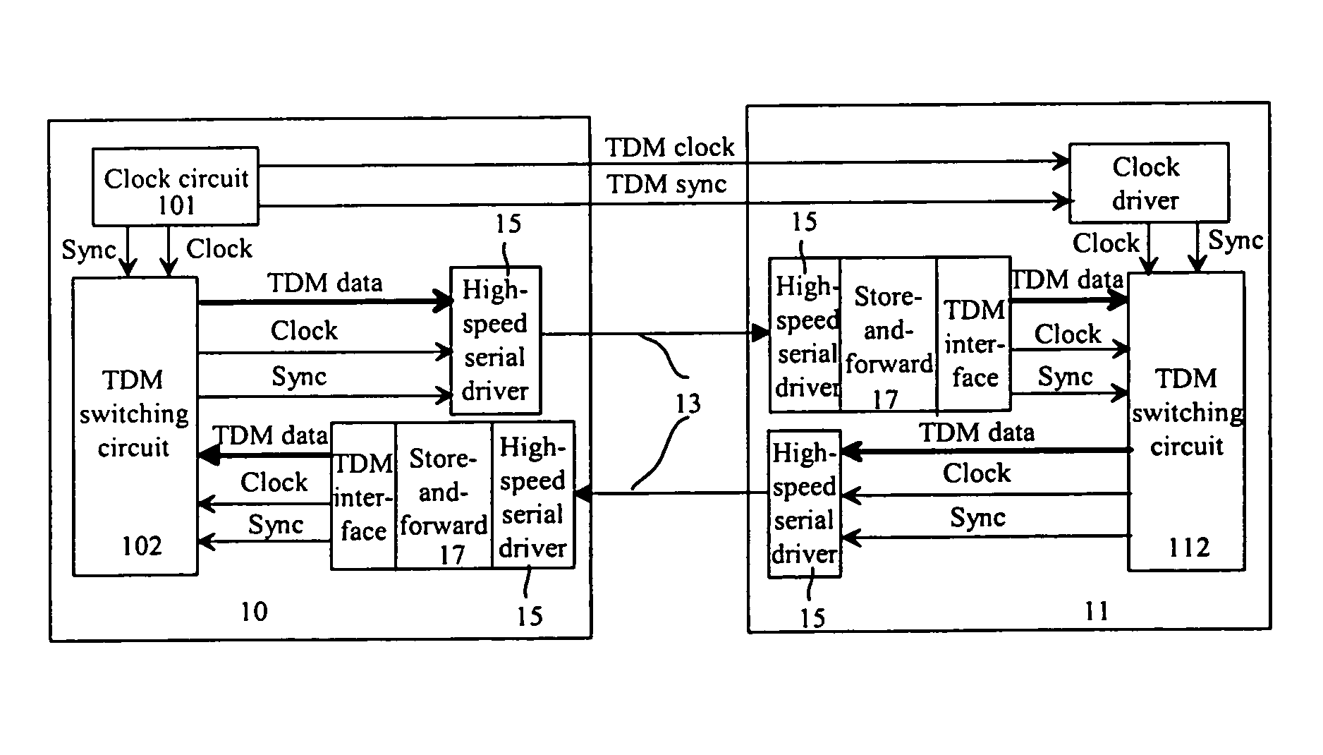
[0031]The invention takes a high-speed serial line on backplane to connect the center switch network board and every service board and to multiplex or interleave / de-multiplex or de-interleave the multi-path TDM data for transmission in batch; in this way, the transmission rate and switching capacity on backplane are greatly increased and at the same time the accurate requirement of the transmission clock phase is decreased, and source of signals on backplane is saved; in addition, because of using the differential transmission mode the noise interference and EMI are reduced. Consequently, data transmission quality and reliability of the system is greatly increased.

Problems solved by technology

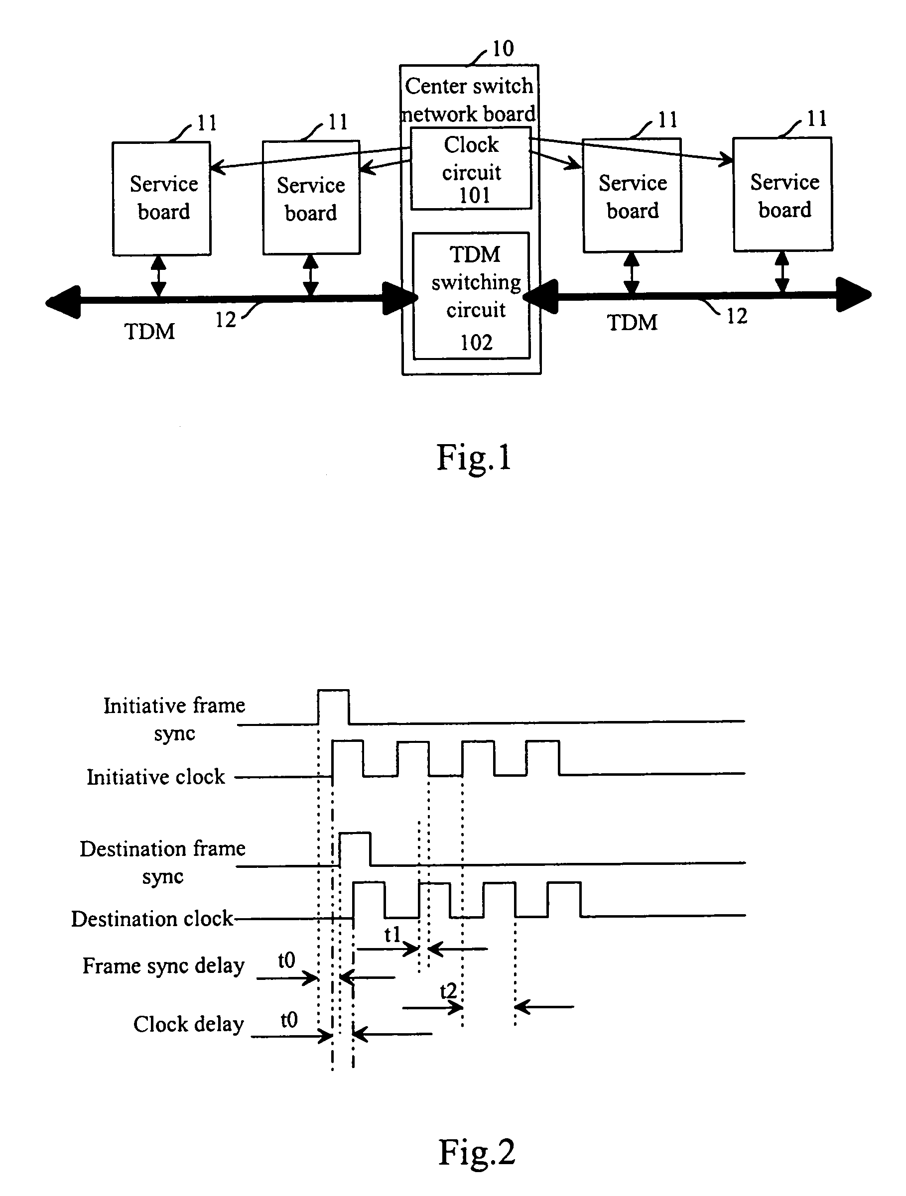
Obviously, the transmission time is asymmetric, and when the transmission frequency is very high, the system reliability is greatly reduced, which means that the system capacity cannot be further increased.
Therefore, clock synchronization is a bottleneck of traditional data transmission based on backplane bus with strict synchronization.
There are disadvantages for the bus mode of signal transmission: a large area, a long distance, many slots, density pins, serious switching noise and electromagnetic interference (EMI) etc., when they are not dealt with adequately, there will be serious signal reflection and interference that cause signal distortion.
In this case, the transmission rate is limited for the system reliability.
In order to increase transmission capacity of backplane circuit, increasing number of transmission signals is a fundamental method, but this is implemented at a cost of a complex system structure, reliability and performance, and the number of transmission signals is limited.
1) it requires strict synchronization, i.e. phase between the frame signal and clock signal should be aligned more strictly;
2) There are disadvantages for the bus mode of signal transmission: a large area, a long distance, many slots, density pins, serious switching noise and electromagnetic interference (EMI) etc. Strict synchronization is very difficult. The transmission rate is greatly limited in order to guarantee system reliability;
3) no matter whether the clock signal is distributed with point-to-point mode or bus mode, since the distance and distributed parameters between different slots are different, the time delay is different;
4) In order to increase transmission capacity of backplane circuit, increasing number of transmission signals is a fundamental method, but this is implemented at a cost of a complex system structure, reliability and performance, and the number of transmission signals is limited.

Method used


Image

  • Method based on backboard transmitting time division multiplexing circuit data and a bridge connector
  • Method based on backboard transmitting time division multiplexing circuit data and a bridge connector
  • Method based on backboard transmitting time division multiplexing circuit data and a bridge connector

Examples


Embodiment Construction

[0046]The invention will be described in more detail with reference to the drawings.

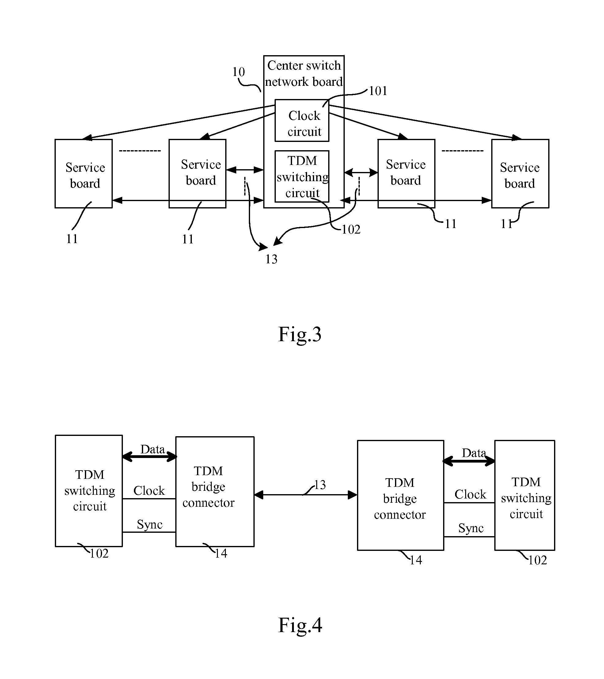
[0047]FIG. 3 shows a diagram of the invention for TDM concentrated switching with high-speed serial line. The clock circuit 101 of the center switch network board 10 provides synchronous and clock signal, which can be distributed by point-to-point mode or bus mode, to service boards 11. Between the TDM switching circuit 102 and the service boards 11 there is a high-speed serial line 13 for data transmission with point-to-point mode.

[0048]FIG. 4 shows a TDM switching structure with TDM bridge connector for the invention. Data, clock and sync signals of the TDM switching circuit 102 are all connected to the TDM bridge connector 14. After multiplexed / de-multiplexed, the TDM data from the TDM switching circuit are transmitted by the TDM bridge connector 14 through the high-speed serial line 13 on the backplane.

[0049]The TDM bridge connector 14 includes: a TDM high-speed serial transmitting adaptive circu...


PUM


Abstract

A method for multi-path TDM data transmission includes: applying a plurality of high-speed serial lines to connect a center switch network board to a plurality of service boards; multiplexing multi-path TDM data from the center switch network board at transmitting side, and transmitting TDM data multiplexed in batch via one of the high-speed serial lines to one of the service boards; at receiving side, serial receiving the TDM data multiplexed and de-multiplexing the TDM data multiplexed to multiple TDM paths. The TDM bridge connector includes: a TDM high-speed serial transmitting adaptive circuit, and a TDM high-speed serial receiving adaptive circuit and a clock control circuit. The invention increases greatly transmission capacity and looses the requirement of clock synchronization, so the system reliability is greatly raised.

Description

FIELD OF THE TECHNOLOGY[0001]The invention generally relates to the time division multiplexing (TDM) technology, specifically to a TDM data transmission method on the backplane and a TDM bridge connector thereof.BACKGROUND OF THE INVENTION[0002]Along with the differential signal level getting lower, noise immunity and transmission rate are getting higher, it is required that the transmission capacity should be getting higher. Traditionally, the TDM centralized switching structure is shown in FIG. 1, where every service board shares the TDM bus 12, and the center switch network board distributes clock, for data transmission at backplane circuit, to each service board with a point-to-point mode or a bus mode.[0003]Suppose that clock high-level duration is t, data is transmitted at leading edge of the clock and is sampled at falling edge of the clock, then the time sequence difference of the traditional synchronous data transmission based on backplane is shown in FIG. 2, where phase be...

Claims


Application Information

Patent Timeline
Patent Type & Authority Patents(United States)
IPC IPC(8): H04J3/00H04Q11/04
CPCH04Q11/04H04Q2213/13166H04Q2213/1336H04Q2213/13292H04Q2213/13214
Inventor LI, ZHENYAWU, GUZHENGYU, QUANXIE, SHOUBOWEI, KONGGANG
Owner HUAWEI TECH CO LTD
Learn More