
Microwave plasma sterilizing method and device

a technology which is applied in the field of sterilization method and device, can solve the problems of inability to use the method for humidity-sensitive materials (such as paper), and the application is limited to metal and glass products, and achieves the effect of effective sterilization and high processing tim

Inactive Publication Date: 2010-04-20
JAPAN SCI & TECH CORP
View PDF35 Cites 7 Cited by
  • Summary
  • Abstract
  • Description
  • Claims
  • Application Information

AI Technical Summary

Benefits of technology

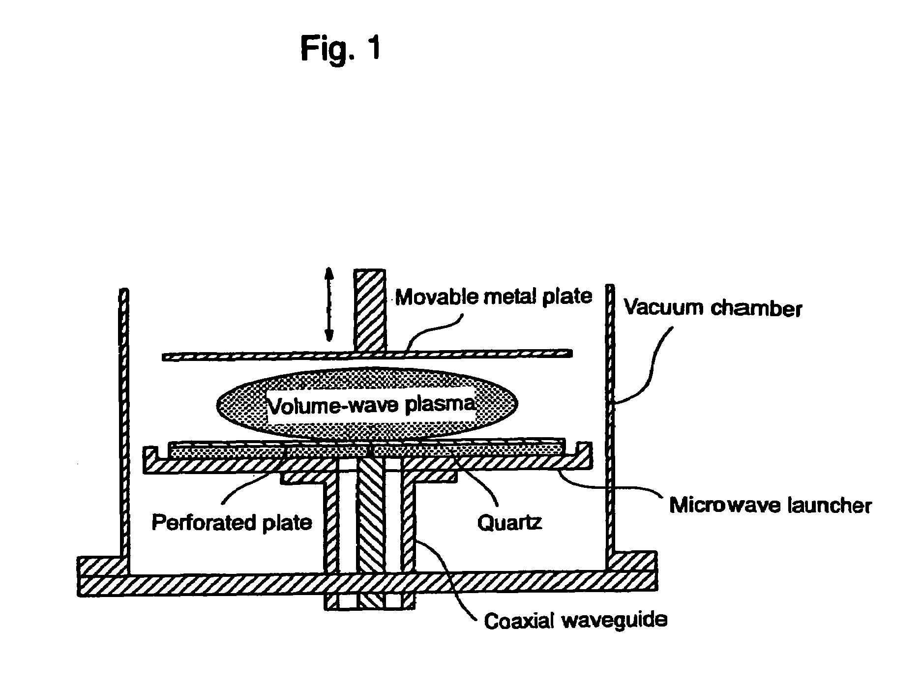
This patent describes a new plasma sterilization method and device that uses volume-wave plasma excited by microwave pulses in oxygen gas instead of conventional surface-wave plasma. The device includes a microwave generator and a vacuum chamber with a gas inlet, outlet for a pump, and a movable metal plate. The microwave launcher is a sandwiched structure with a quartz plate for generating volume-wave plasma. The object being sterilized is placed between the microwave launcher and the movable metal plate. The technical effect of this invention is that it provides a more efficient and effective plasma sterilization method and device.

Problems solved by technology

Dry-heat sterilization uses high temperatures of 160 to 180° C. or above and this application is limited to metal and glass products.
Steam under pressure sterilization also uses high temperatures and these applications are also limited to metal and glass products.
Moreover, this method cannot be used for humidity-sensitive materials (such as paper).
Radiosterilization has the risk of a health hazard to the human body.
Radiosterilization is not effective to areas where the radiation does not reach.
Ethylene oxide gas sterilization requires very careful handling due to the toxicity and flammability of the gas used.
The difficult disposal of residual materials after sterilization also poses a problem.
In principle, most of them use a high temperature to sterilize and as such involve handling problems.
Chlorine gas is toxic and plasma occurs on the surface of the discharging electrode, and is not effective.
The inside of a package is difficult to sterilize and as such sterilization is limited to the exterior of the package.
These techniques are not applicable to resinous medical instruments such as catheters and injection devices and medical instruments that require sterilization of their insides such as vacuum tubes for drawing blood.
The objects that can be sterilized are also limited due to thermal problems related to plasma irradiation.
Other sterilization methods have various limitations and hazards due to their use of high temperature, high pressure and toxic gas.

Method used


Image

  • Microwave plasma sterilizing method and device
  • Microwave plasma sterilizing method and device
  • Microwave plasma sterilizing method and device

Examples


working example 1

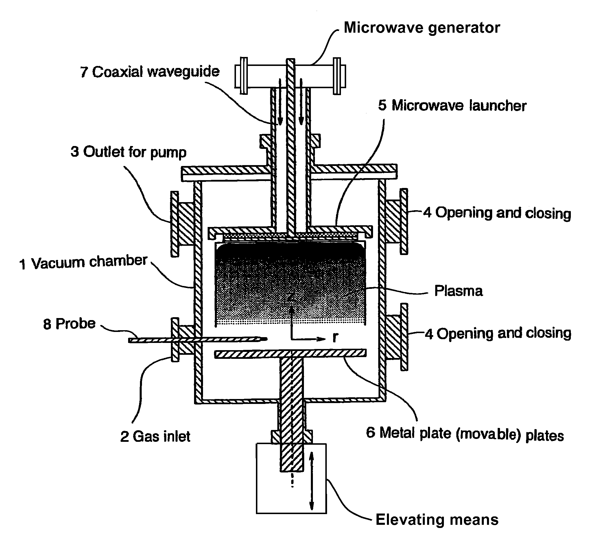
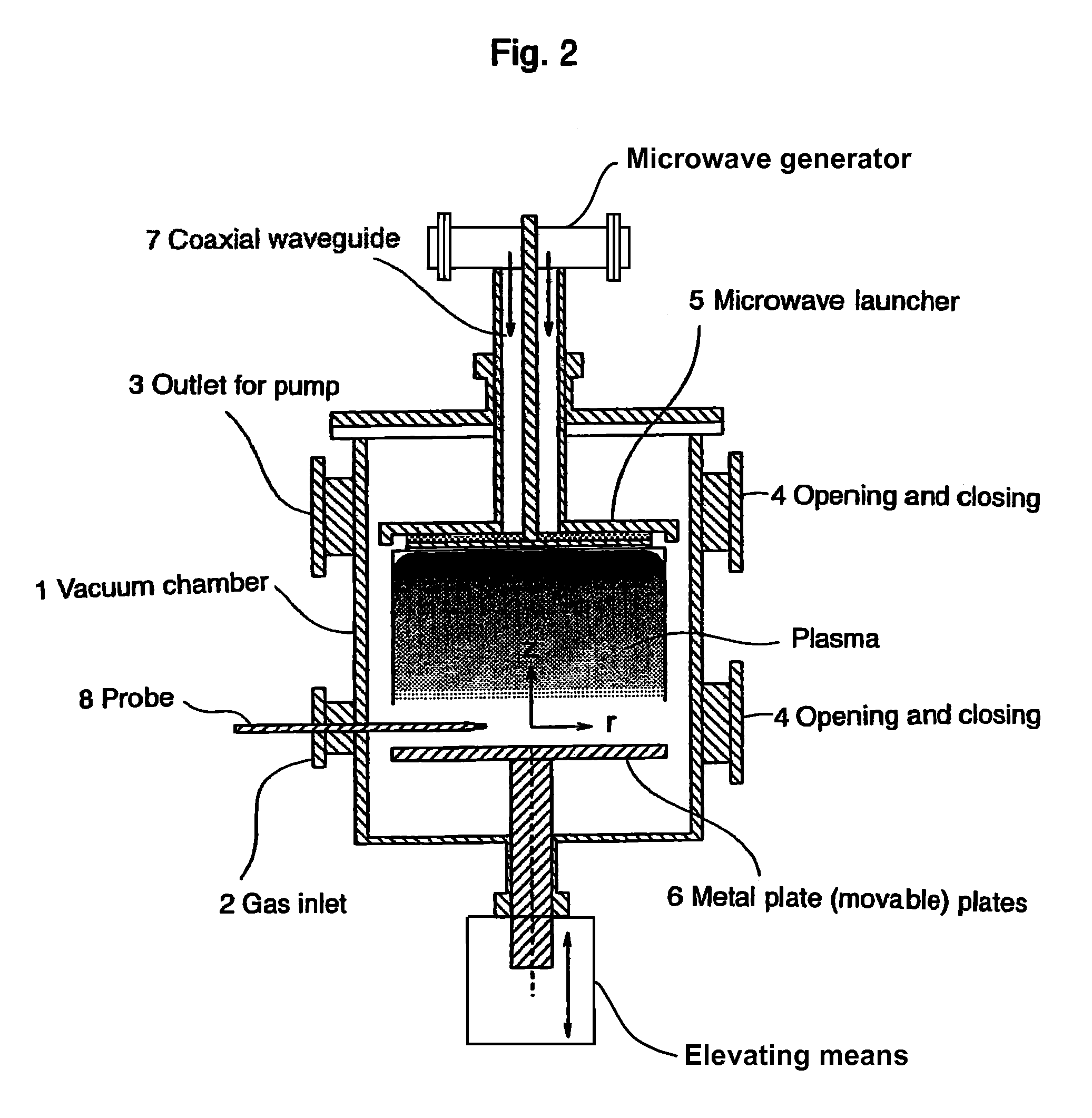
[0023]FIG. 2 shows a working example of the microwave plasma sterilizing device of this invention. FIGS. 2 and 3 illustrate and identify stainless steel cylindrical vacuum chamber 1, gas inlet 2, outlet 3 for the pump, upper and lower opening and closing plates 4, microwave launcher 5, movable metal plate 6, coaxial waveguide 7 for introducing microwaves from an external microwave generator, probe 8 for detecting the condition of the vacuum chamber, perforated plate 9, many holes 10 of a specified diameter perforated through the perforated plate, quartz plate 11, and vacuum seal 12.

[0024]The stainless steel cylindrical vacuum chamber 1 of this working example is 500 mm high and has an inside diameter of 250 mm. An aluminum microwave launcher 5 is arranged in the vacuum chamber 1. A movable metal plate 6, 220 mm in diameter, is arranged opposite to the microwave launcher 5. The movable metal plate 6 is connected to an elevating means to allow vertical positional adjustment.

[0025]FIG....

working example 2

[0028]FIG. 4 shows another working example of the microwave plasma sterilizing device of this invention. The figure depicts the structure of the vacuum chamber of a large-area plasma device. The reference numerals are the same as used in FIGS. 2 and 3. The stainless steel cylindrical vacuum chamber 1 is 350 mm high and has an inside diameter of 600 mm. The microwave launcher 5 is suspended from above in the vacuum chamber 1. The quartz plate 11 is 10 mm thick and has a diameter of 500 mm. The diameter of the holes 10 through perforated plate 9 are 4 mm, 6 mm or 10 mm.

[0029]A 2.45 GHz microwave oscillator (not shown) with 1.5 kW output transmits microwaves to the microwave launcher 5 after coaxial conversion at the coaxial waveguide 7. In this working example, we used Ar gas at 74 m Torr gas pressure to generate plasma. As we increased the incident power from 0.2 kW to 1.5 kW, plasma was generated at the center of the launcher 5 and gradually expanded around the launcher's periphery....


PUM

PropertyMeasurementUnit
temperaturesaaaaaaaaaa
diameteraaaaaaaaaa
diameteraaaaaaaaaa

Abstract

A microwave inlet for introducing microwaves (coaxial waveguide) and a microwave launcher for generating volume-wave plasma are arranged on one side in a vacuum chamber, and a movable metal plate is arranged opposite to the microwave launcher on the other side in the vacuum chamber. The microwave launcher has a sandwiched structure where a quartz plate is sandwiched by a perforated plate having many holes of a specified diameter. Microwaves are introduced from an external microwave generator to the microwave launcher in, for example, oxygen gas, a mixture of helium gas and oxygen gas, a mixture of argon gas and oxygen gas, or a mixture of oxygen gas and nitrogen gas to change the spatial distribution of the electric field intensity, whereby the volume-wave plasma discharge is diffused to the entire inner space of the vacuum chamber by microwaves leaking through the holes in the perforated plate. The sterilizing method and the device of this invention use microwave discharge plasma that enables sterilization inside a perforated resinous package, such as a package of medical instruments in a vacuum chamber.

Description

FIELD OF THE INVENTION[0001]This invention relates to a sterilizing method and device. Specifically, this invention relates to a sterilizing method and device using microwave plasma for disinfection and sterilization of medical instruments contained in resinous packages and for sterilization of foods in packages and bags for foods.BACKGROUND ART[0002]Conventional disinfection and sterilization methods for medical instruments and disinfection methods for foods in packages and bags for foods include dry-heat sterilization, steam under pressure sterilization, radiosterilization, ethylene oxide gas sterilization and plasma sterilization.[0003]Dry-heat sterilization uses high temperatures of 160 to 180° C. or above and this application is limited to metal and glass products. Sixty minutes are required to complete dry-heat sterilization. Steam under pressure sterilization also uses high temperatures and these applications are also limited to metal and glass products. Twenty minutes are re...

Claims


Application Information

Patent Timeline
Patent Type & Authority Patents(United States)
IPC IPC(8): A61L2/12A61L2/14H01J37/32H05H1/46
CPCA61L2/14H01J37/32568H01J37/32238H01J37/32192
Inventor NAGATSU, MASAAKI
Owner JAPAN SCI & TECH CORP
Learn More