
Image forming method, planographic printing plate precursor, and planographic printing method

a technology of image forming and planographic printing, applied in the direction of instruments, diffusion transfer processes, photomechanical equipment, etc., can solve the problems of large fog, low work efficiency, and high work difficulty, and achieve satisfactory fine line reproducibility, high image quality, and high sensitivity and white light safety.

Inactive Publication Date: 2010-04-20
FUJIFILM CORP
View PDF30 Cites 7 Cited by
  • Summary
  • Abstract
  • Description
  • Claims
  • Application Information

AI Technical Summary

Benefits of technology

The present invention relates to an image forming method, a planographic printing plate precursor, and a planographic printing plate using a light source that emits light in the range of 250 to 420 nm. The invention addresses the problem of fogging and defects when using conventional high-sensitivity laser recording type plates in the market. The invention proposes a method of using a photosensitive composition containing specific components to improve the safety and workability of the printing process. Additionally, the invention proposes a method of developing a printing plate using a printing machine to simplify the production process and improve printing durability.

Problems solved by technology

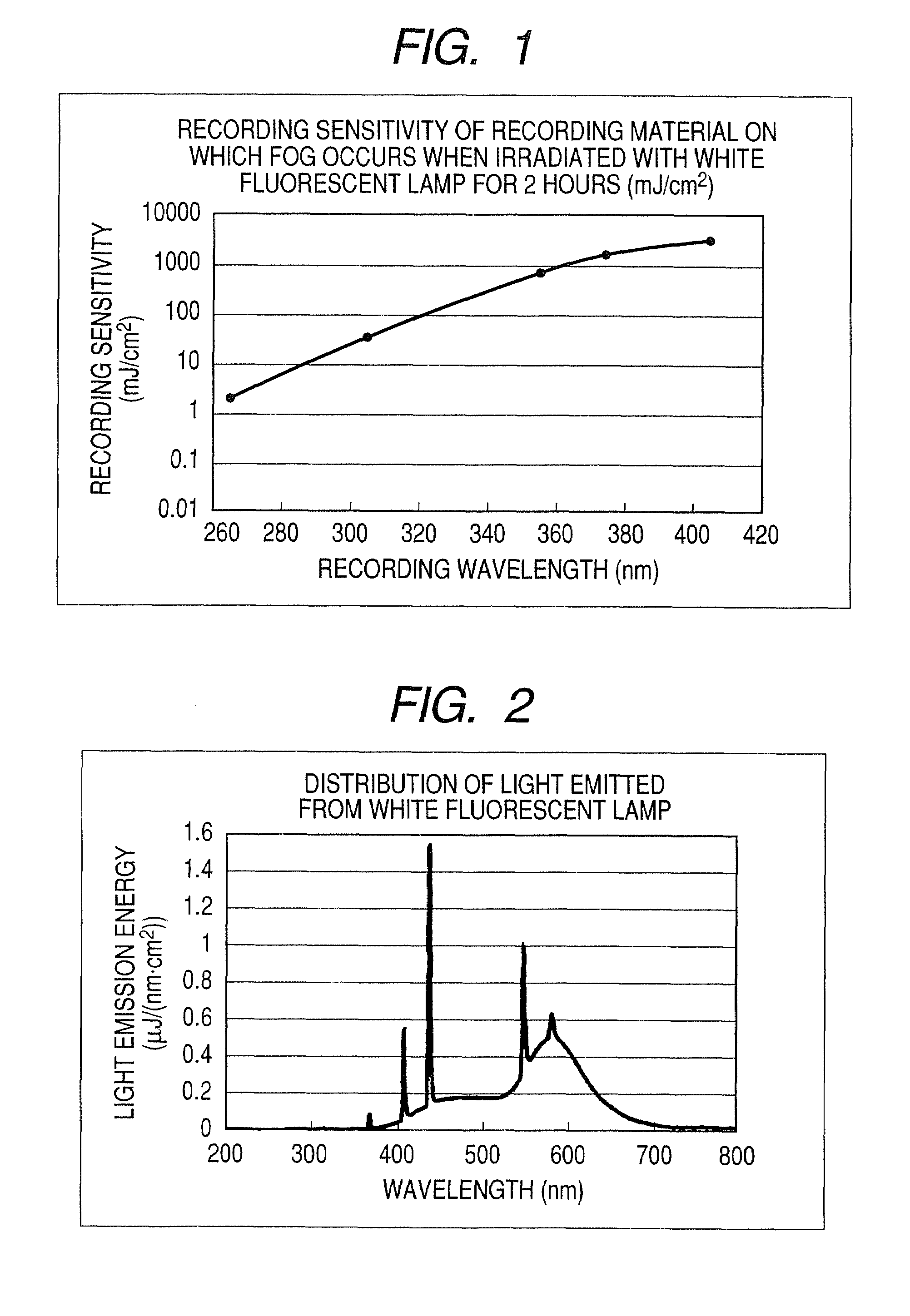
However, the conventional high-sensitivity laser recording type planographic printing plate has a problem such that, when it is subjected to exposure using an Ar (488, 514.5 nm) or FD-YAG (532 nm) laser internal drum type platesetter, which is most commonly used on the market, a fog is likely to occur.
When the other side is a non-image portion, a thin fog (like when development is insufficient) occurs.
All of these pieces of work need to be performed under dim red light, resulting in considerably poor workability.
One of the recent challenges is to eliminate or simplify such a wet process which is additionally performed.
However, the photoinitiator used therein has a problem on sensitivity and a fog after exposure.
However, the adhesion between the upper layer and the lower layer is insufficient, so that printing durability is still poor.
However, it was found that, in the case of the above-described method of forming an image by coalescence of the microparticle due to simple thermal fusion bonding, although good development-on-machine ability is exhibited, image strength is weak, so that printing durability is insufficient.
When these techniques are applied to a development-on-machine-type planographic printing plate precursor, an improvement in the adhesiveness leads to a degradation in resistance to stain.
On the other hand, when an image recording method which utilizes light of ultraviolet to a visible region is applied to such a non-processed printing plate which does not require a development process using a developer solution, an image recording layer is not fixed and is still kept photosensitive to room light even after exposure.
If otherwise, i.e., for example, if the plate is handled under white light after exposure, a fog occurs in an image recording layer, the layer remains in a non-image portion, leading to printing stain.
Therefore, even printing machine work which conventionally does not require safe light needs to be performed under the environment of safe light, resulting in interference with printing work, such as color adjustment or the like.

Method used


Image

  • Image forming method, planographic printing plate precursor, and planographic printing method
  • Image forming method, planographic printing plate precursor, and planographic printing method
  • Image forming method, planographic printing plate precursor, and planographic printing method

Examples


examples

[0371]Hereinafter, the present invention will be described in detail by way of examples. The present invention is not limited to these examples.

[0372]1. Preparation of Support

[0373]A melt of a JIS A1050 aluminum alloy containing 99.5% by mass or more aluminum, 0.30% by mass Fe, 0.10% by mass Si, 0.02% by mass Ti, and 0.013% by mass Cu was subjected to a cleaning treatment, followed by casting. In this cleaning treatment, the melt was degassed to remove unnecessary gas, such as hydrogen or the like, and was filtered through a ceramic tube filter. Casting was conducted using a DC casting method. The coagulated ingot plate having a wall thickness of 500 mm was shaved from a surface thereof by a depth of 10 mm, and thereafter, the plate was subjected to a homogenization treatment at 550° C. for 10 hours so that an intermetallic compound was not formed into a rough and large mass. Then, the plate was hot-rolled at 400° C. and was then annealed at 500° C. for 60 seconds in a continuous an...

examples 1 to 9

[0407]The planographic printing plate precursors (1) to (9) fabricated as described above were used to carry out image formation and printing to evaluate sensitivity, fine line reproducibility, and white light safety. Hereinafter, an exposure method, a development method, a printing method, and an evaluation method used herein will be described. The planographic printing plate precursors used in the examples and the results of evaluation are shown in Table 1.

examples 10 and 11

[0408]Exposure and printing were performed in a manner similar to that of Examples 1 and 2, except that a one-pixel drawing time was changed as shown in Table 1. The result is shown in Table 1.


PUM

PropertyMeasurementUnit
wavelength rangeaaaaaaaaaa
wavelengthaaaaaaaaaa

Abstract

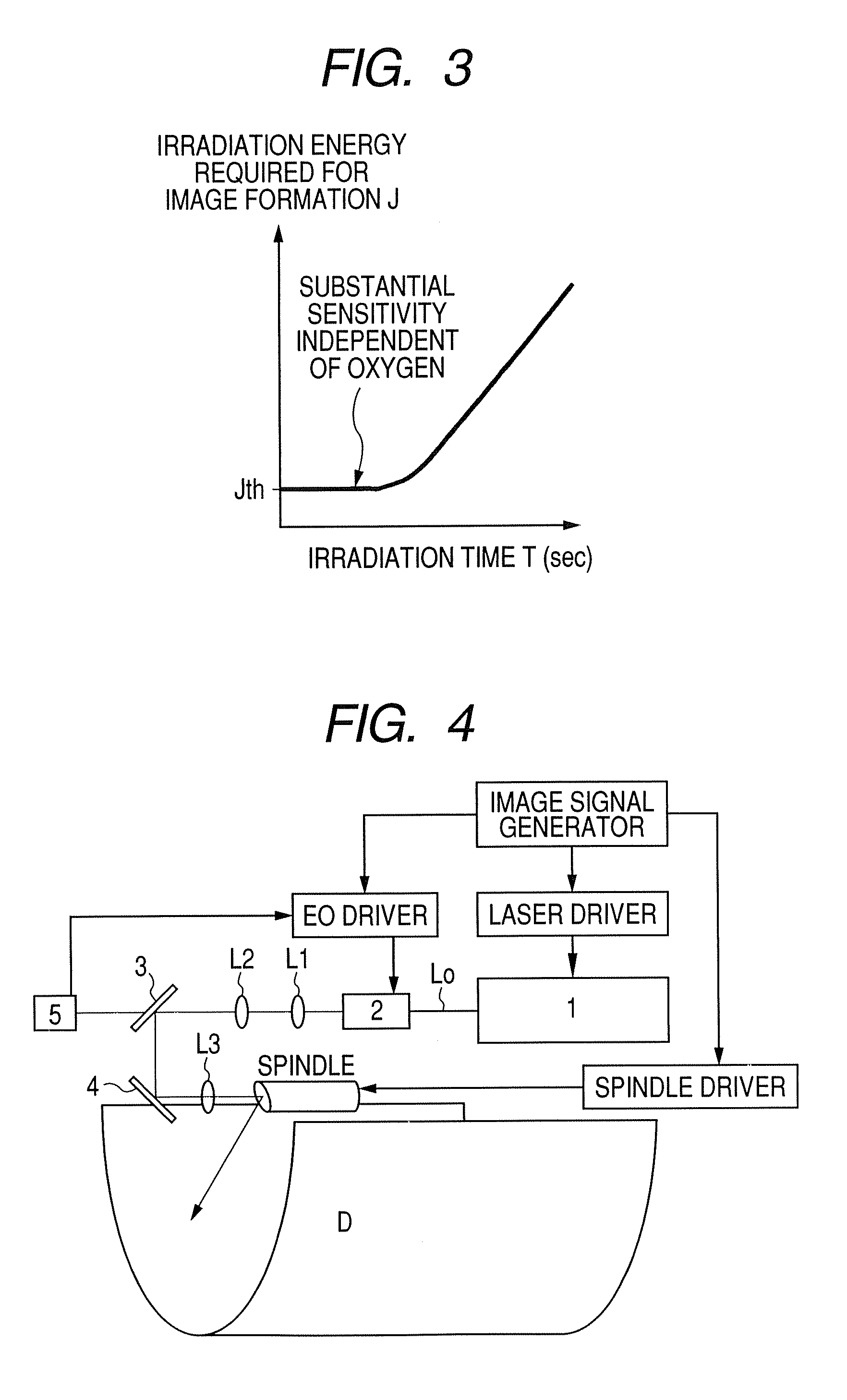
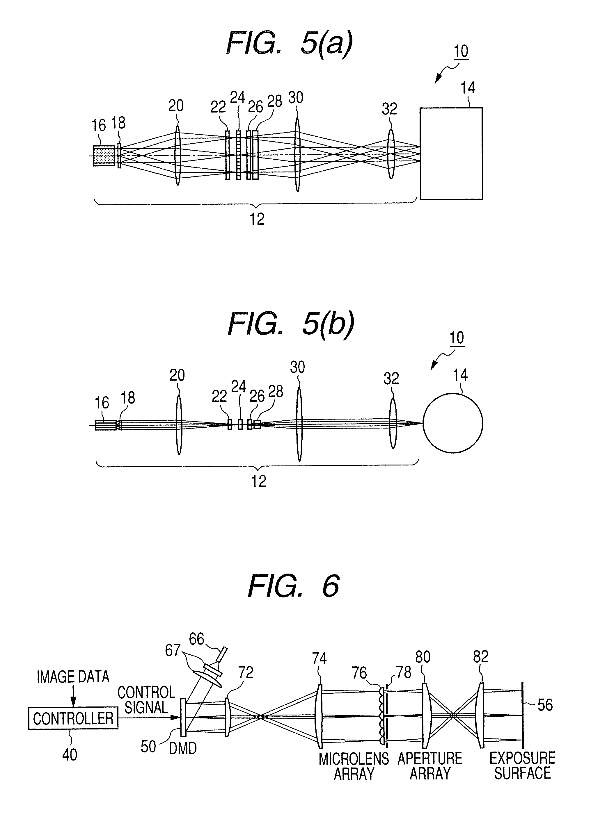
An image forming method in which a planographic printing plate precursor having, on a support, an image recording layer containing (A) a polymerization initiator, (B) a polymerizable compound, and (C) a binder polymer, and having photosensitivity in a wavelength range of 250 nm to 420 nm, is subjected to exposure using laser light in the wavelength range of 250 nm to 420 nm, and a one-pixel drawing time is one millisecond or less, a planographic printing plate precursor having the image recording layer which further contains (D) a compound having a polymerizable group and a support adsorptive group, or (F) a filler, and a planographic printing method including development-on-machine, are provided.

Description

TECHNICAL FIELD[0001]The present invention relates to an image forming method, a planographic printing plate precursor, and a planographic printing method in the field of printing. More specifically, the present invention relates to an image forming method, a planographic printing plate precursor, and a planographic printing method which employ a light source which emits light having a wavelength in the range of 250 to 420 nm.BACKGROUND ART[0002]Recently, in the field of planographic printing, a computer-to-plate technique has been developed in which a planographic printing plate precursor is directly subjected to laser exposure, without via a lithographic film, based on digital data from a computer or the like to produce a plate, and a high-sensitivity laser recording type planographic printing plate for use in such a technique has been developed.[0003]However, the conventional high-sensitivity laser recording type planographic printing plate has a problem such that, when it is sub...

Claims


Application Information

Patent Timeline
Patent Type & Authority Patents(United States)
IPC IPC(8): G03F7/11B41N1/08G03F7/26B41N1/14G03F7/00G03F7/004G03F7/027G03F7/20
CPCG03F7/2055
Inventor HOSHI, SATOSHISUNAGAWA, HIROSHIINNO, TOSHIFUMIMAKINO, NAONORIKUMADA, GAKUAOSHIMA, NORIO
Owner FUJIFILM CORP
Learn More