
Planar micro-discharge gas detector

a gas detector and micro-discharge technology, applied in the field of gas detection, can solve the problems of spectroscopic identification of gases present in discharges that require a relatively large, complex and expensive spectrometer to analyze the light from the discharg

Inactive Publication Date: 2010-04-20
HERRING CYRUS M
View PDF24 Cites 20 Cited by
  • Summary
  • Abstract
  • Description
  • Claims
  • Application Information

AI Technical Summary

Benefits of technology

"The patent is about a new gas detector that can quickly and accurately detect nitric oxide in exhaust gas mixtures. The detector uses a special gas discharge device that emits light when gas molecules enter a small electric field. The light is then detected by a photosensor, which can identify different gases based on their electronic characteristics. The detector is designed to be durable and can withstand high temperatures, making it suitable for use in high-temperature environments. The detector can also be used for gas chromatography analysis, where the gas is forced to flow through the device and the light emitted is measured. The detector is coated with an insulating material and uses alternating current to create a discharge, which helps to self-limit the current and prevent damage to the electrodes. Overall, the patent describes a new and improved gas detector that can provide real-time monitoring of nitric oxide in exhaust gas and is sensitive, accurate, and cost-effective."

Problems solved by technology

The most sensitive and differentiating gas detectors used in gas chromatography are also the most expensive and bulky.
The spectroscopic identification of gases present in a discharge often requires a relatively large, complex and expensive spectrometer to analyze the light from the discharge.

Method used


Image

  • Planar micro-discharge gas detector
  • Planar micro-discharge gas detector
  • Planar micro-discharge gas detector

Examples


Embodiment Construction

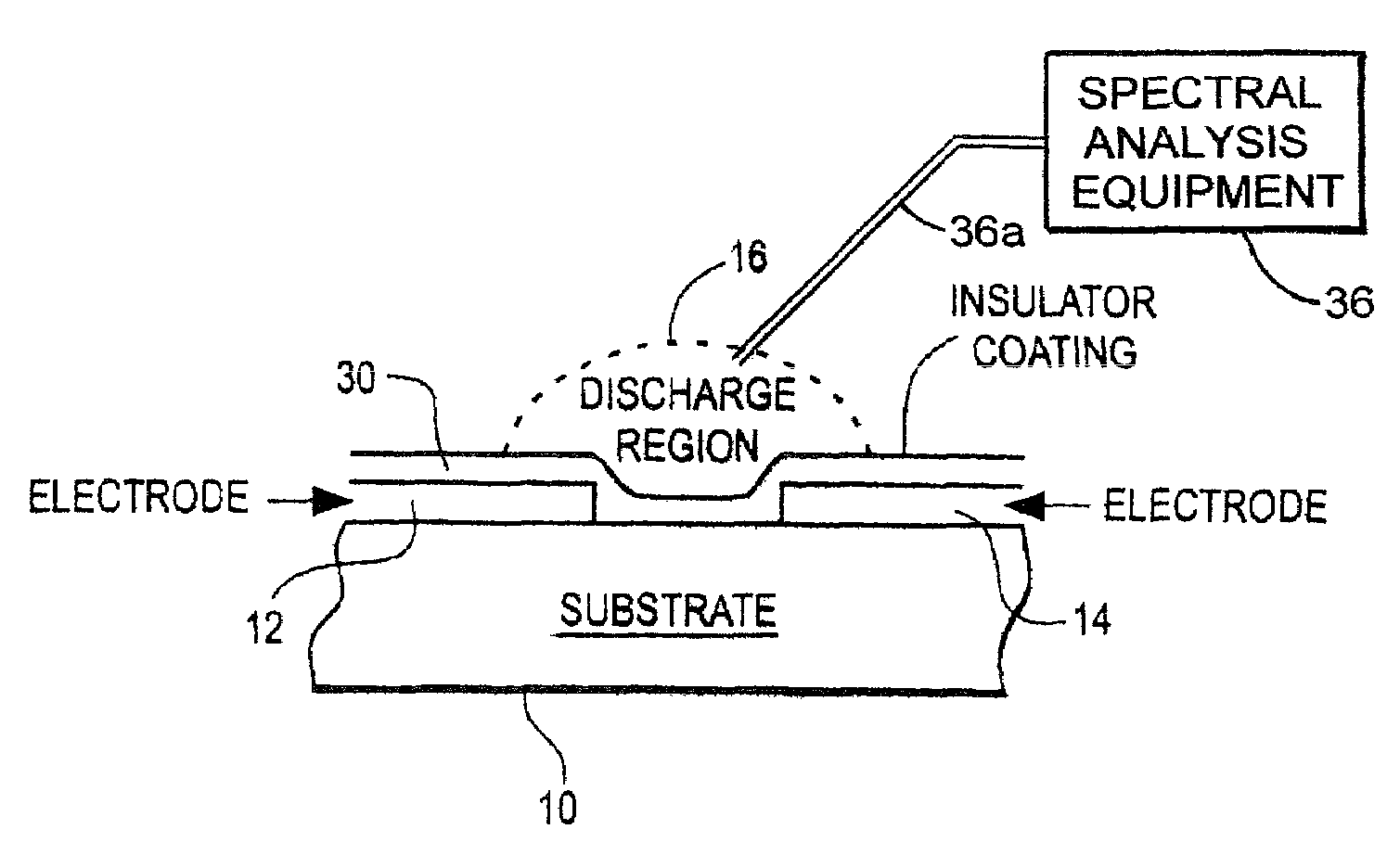
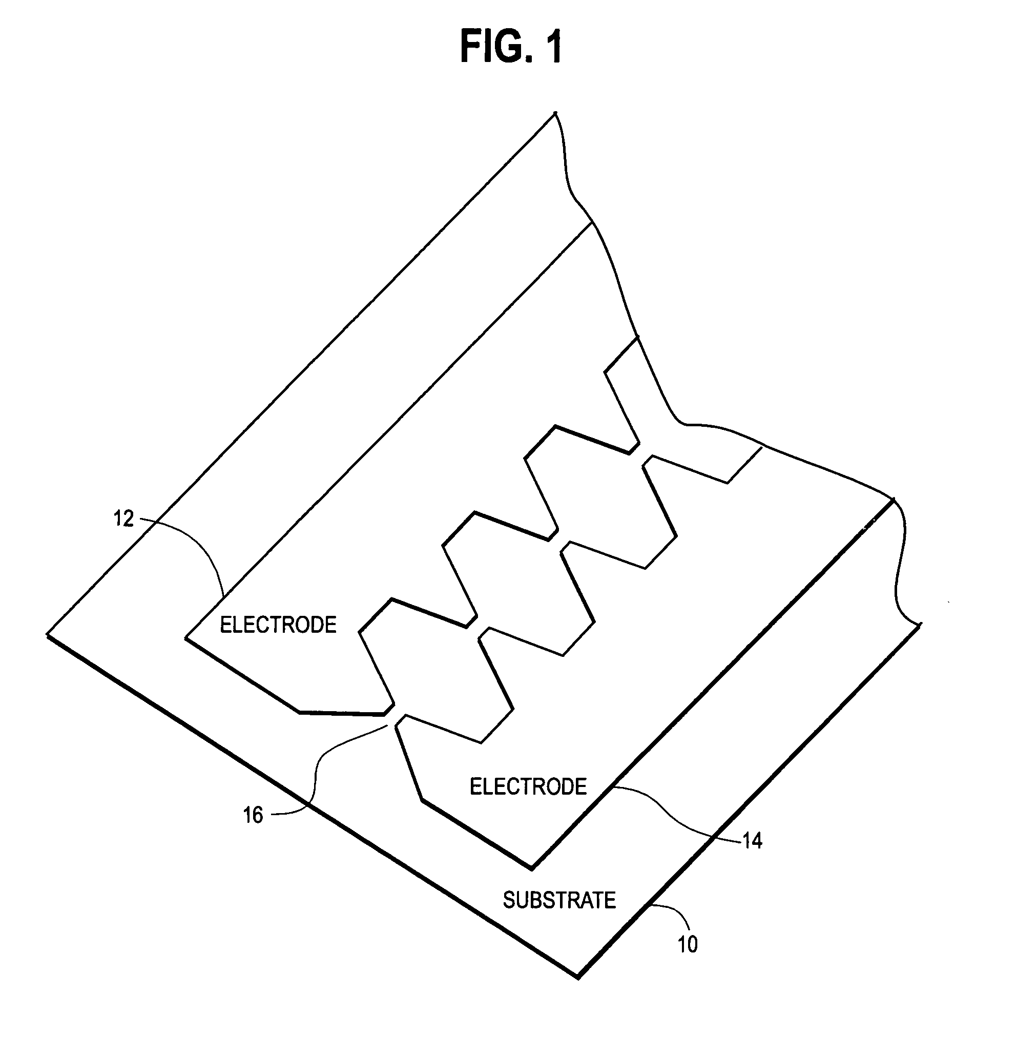
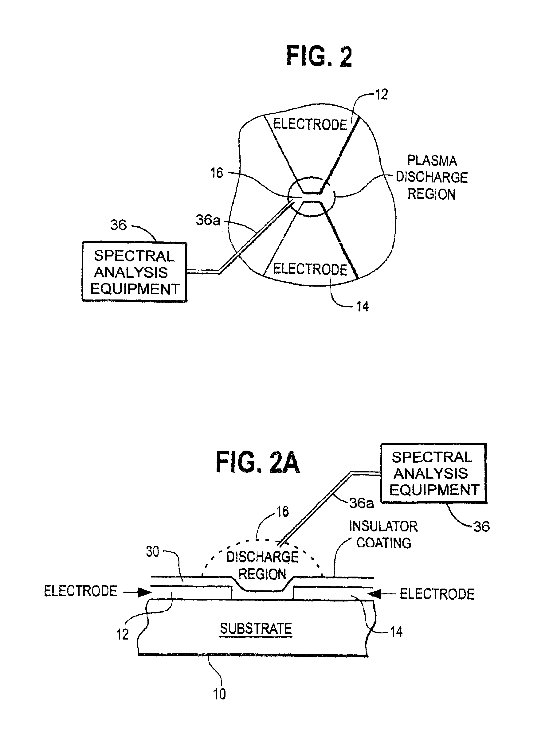
[0016]I have designed a micro-discharge device that can be operated with an AC power supply in gases at pressure ranges from a few milli-Torr to a few atmospheres. The device has two electrodes typically separated by a gap of several tens of microns (the gap may be one micron to 500 microns). A discharge is formed in the gas in the gap by applying an AC voltage between the two electrodes.

[0017]In fact, it is the small size of the discharge that allows it to operate in a stable manner at atmospheric pressure. Larger dimension devices (greater than ˜200 microns) tend to exhibit instability in the discharge which results in noise, limiting the sensitivity. Atmospheric pressure operation is an advantage since external pumps are not required as they are in several competing detector technologies.

[0018]If a pump is used, thus decreasing the operating pressure of the discharge, the optical radiation emitted from the discharge will have a reduced linewidth. This will allow the identificatio...


PUM

PropertyMeasurementUnit
electric fieldaaaaaaaaaa
distanceaaaaaaaaaa
distanceaaaaaaaaaa

Abstract

A micro-sized gas detecting device with two electrodes separated by a gap of width ranging from 1 to 500 microns, where the detection is based on emission spectroscopy of gases in an electric discharge across the gap (discharge region) as the gas flows through the region. The characteristic light emitted by molecules during the discharge can be detected directly with photodiodes or transferred through optical fiber and detected with remote optical sensing components. The device can have single or multiple discharge regions in an array so that light emitted can be monitored at different wavelengths simultaneously. The device can operate under gaseous pressure ranging from a few milli-Torr to a few atmospheres. The device consumes little power (50 mW-100 mW) and can be powered with an alternating current and has the potential to be battery powered.

Description

CROSS REFERENCE TO RELATED APPLICATION[0001]This application claims the benefit of U.S. Provisional Application Ser. No. 60 / 502,676, Sep. 12, 2003.FIELD OF INVENTION[0002]This invention pertains to gas detection, especially for nitric oxide in exhaust gas, and gas chromatography detection and analysis.BACKGROUND OF INVENTION[0003]Nitric oxide (NO), along with the other hazardous nitrogen oxides, is known to be involved in and important to many physiologically or clinically important processes. It is also an increasing concern for its environmental impact. Nitric oxide is commonly produced as a byproduct in the combustion processes. Therefore, there is a substantial need for a gas detector that can provide real-time monitoring of nitric oxide, particularly in exhaust gas mixtures, in a sensitive, accurate and economic manner.[0004]Gas chromatography is a scientific method of gas analysis and identification, including trace gas identification such as chemical agent detection. The most...

Claims


Application Information

Patent Timeline
Patent Type & Authority Patents(United States)
IPC IPC(8): G01N21/25G01J3/30H01J47/00G01T1/185G01T1/18G01J3/443G01N21/00
CPCG01J3/443G01N21/67G01N2030/647
Inventor HERRING, CYRUS M.
Owner HERRING CYRUS M
Learn More