
Wear pads for timing-based surface film servo heads

a surface film and servo head technology, applied in the field of thin film magnetic recording heads with wear pads, can solve the problems of low inductance, amplitude modulation problems, and inability to provide a separate read head, and achieve the effect of preventing negative effects and thin film wearing faster

Inactive Publication Date: 2010-04-20
ADVANCED RES
View PDF51 Cites 0 Cited by
  • Summary
  • Abstract
  • Description
  • Claims
  • Application Information

AI Technical Summary

Benefits of technology

The solution results in a more efficient data writing process with sharper transitions and increased bandwidth, reducing the rise time of written pulses and minimizing media degradation, while allowing for accurate positional control of read heads across the tape.

Problems solved by technology

It is generally not feasible to provide a separate read head for each data track, therefore, the read head(s) must move across the width of the tape (in a translating direction), and center themselves over individual data tracks.
The trend toward thinner and thinner magnetic tape layers causes amplitude modulation problems with this and other amplitude based heads.
Such a head has very low inductance; however, it is extremely difficult to manufacture.
To date, pure thin film heads are generally not utilized for time based servo heads and are not seen as a practical way to produce such a magnetic head.
Hence, there is a large amount of unnecessary ferrite inductance.
In other words, as a result of the relatively large amount of extraneous ferrite, an unnecessarily high amount of inductance is created.
Therefore, to produce a relatively small amount of flux leakage through a small gap in the thin film, very high levels of voltage are required to generate sufficient magnetic flux throughout the relatively large core.

Method used


Image

  • Wear pads for timing-based surface film servo heads
  • Wear pads for timing-based surface film servo heads
  • Wear pads for timing-based surface film servo heads

Examples


Embodiment Construction

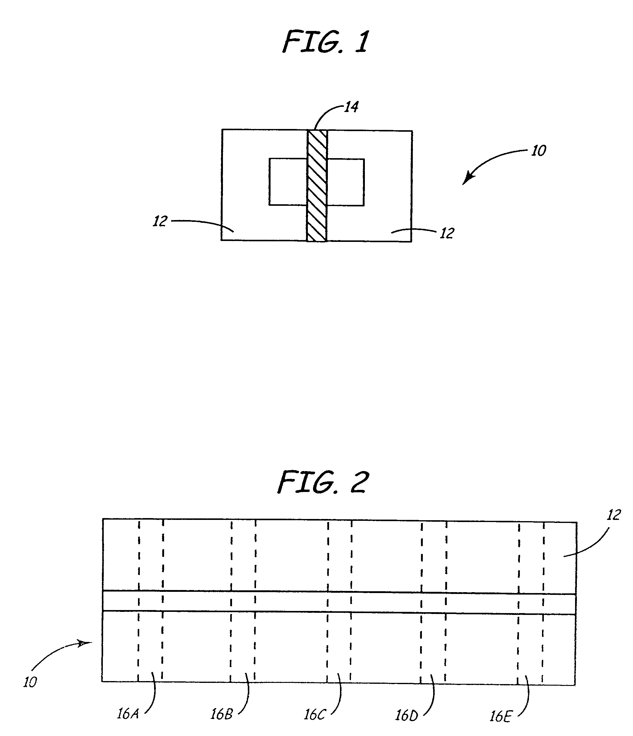
[0065]The present invention is a multi-channel head and method of making the same. Referring to FIG. 1, a substrate 10 is created by glass bonding two C-shaped ferrite blocks 12 to a medially disposed ceramic member 14. The sizes, shapes and relative proportions of the ferrite blocks 12 and ceramic member 14 may vary as dictated by the desired parameters of the completed recording head. Furthermore, the choice of materials may also vary so long as blocks 12 remain magnetically permeable while member 14 remains substantially magnetically impermeable. FIG. 2 is a top view of the substrate 10.

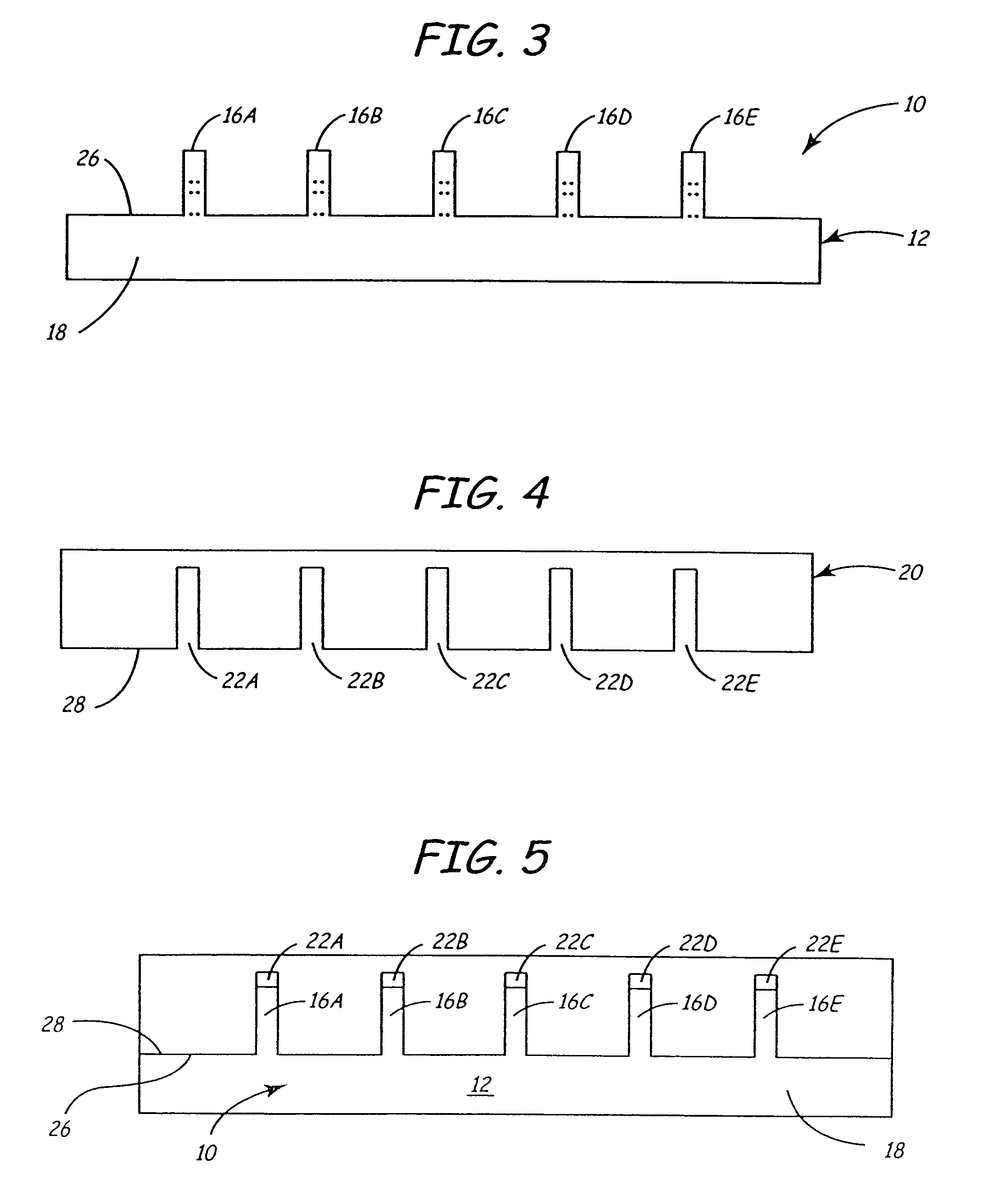
[0066]Referring to FIG. 3, substrate 10 is diced so as to form a plurality of columns 16A-16E which remain adhered to base 18. Columns 16A-16E are also shown by the dashed lines in FIG. 2, which illustrates how each column will have a ceramic portion (sub-gap) bonded between two ferrite poles. The dashed lines are merely illustrative of future columns, as the substrate 10 in FIG. 2 has yet to be d...


PUM

PropertyMeasurementUnit
inductancesaaaaaaaaaa
spacingaaaaaaaaaa

Abstract

A thin film magnetic recording head is provided with a tape bearing surface that has magnetically isolated channels while still providing a maximum continuous surface area with which to engage the media. This can be accomplished by providing spaces in the magnetically permeable thin film that are large enough to prevent cross-talk between the channels, but small enough to prevent significant interference with the moving media. Alternatively, magnetically impermeable thin film spacers can be provided to magnetically isolate each of the channels. The spacers are generally even with the magnetically permeable thin film so as to provide a continuous media-bearing surface.

Description

CROSS-REFERENCE TO RELATED APPLICATION[0001]This Application is a divisional application of U.S. Ser. No. 10 / 277,773, filed Oct. 22, 2002, now U.S. Pat. No. 6,989,960, which is a continuation-in-part of U.S. Ser. No. 09 / 475,420 filed Dec. 30, 1999, now U.S. Pat. No. 6,496,328, the subject matter of which is hereby incorporated by reference in its entirety.FIELD OF THE INVENTION[0002]This invention relates generally to magnetic recording heads and more particularly to thin film magnetic recording heads having wear pads to minimize media degradation and head wear.BACKGROUND OF THE INVENTION[0003]While a variety of data storage mediums are available, magnetic tape remains a preferred forum for economically storing large amounts of data. In order to facilitate the efficient use of this media, magnetic tape will have a plurality of data tracks extending in a transducing direction of the tape. Once data is recorded onto the tape, one or more data read heads will read the data from those t...

Claims


Application Information

Patent Timeline
Patent Type & Authority Patents(United States)
IPC IPC(8): G11B5/29G11B5/133G11B5/187G11B5/65G11B5/127G11B5/23G11B5/31G11B5/48G11B5/584
CPCG11B5/1276G11B5/1877G11B5/29G11B5/295G11B5/584Y10T29/49052G11B5/4893Y10T29/49046G11B5/3116
Inventor DUGAS, MATTHEW P.
Owner ADVANCED RES
Learn More