Processing method of fine structure and processing equipment for fine structure

a processing method and technology of fine structure, applied in the field of processing method of fine structure and processing equipment for fine structure, can solve the problems of affecting the quality of dough, and affecting the quality of dough, and achieve the effects of excellent throughput, excellent yield, and fine structur

Inactive Publication Date: 2010-05-11
SUMITOMO ELECTRIC IND LTD
View PDF13 Cites 2 Cited by
  • Summary
  • Abstract
  • Description
  • Claims
  • Application Information

AI Technical Summary

Benefits of technology

[0014]According to the aforementioned method or the aforementioned equipment, a fine structure can be processed with an excellent throughput and an excellent yield. Further, the quality of the fine structure can be improved. The aforementioned drive unit may be in any form so far as the same is a drive unit rendering at least two opposed platens usable when a single fine structure is processed, and may be a unit moving the platens, a unit moving the mold, or a unit moving both of the platens and the mold.
[0015]When the molded material is cooled, the total thermal capacity of the opposed platens is reduced by reducing the volume of the opposed platens for physically discharging heat stored in the opposed platens, so that the cooling rate for the opposed platens can be improved.
[0016]The first block is heated when the opposed platens are heated while the second block which is the external member is brought into contact with the first block when the opposed platens are cooled thereby increasing the volume of the opposed platens in cooling and moving heat provided in the first block toward the second block, so that the cooling rate for the opposed platens can be improved.
[0017]Thus, heating efficiency for the opposed platens and cooling efficiency for the opposed platens are improved by pressurizing / heating / molding the molded material while rendering the volume of the opposed platens in heating and the volume of the opposed platens in cooling different from each other, so that the heat cycle of heating and cooling can be reduced. Consequently, the throughput required for processing the fine structure can be improved.
[0018]When the molded material is cooled, a third block which is the external member is brought into contact with the first block after the second block of the opposed platens formed by the first block and the second block in heating of the molded material is separated thereby reducing the total thermal capacity of the opposed platens by reducing the volume of the opposed platens immediately after the heating and physically discharging the heat stored in the opposed platens while bringing the third block which is the external member into contact with the first block in cooling for moving the heat provided in the first block to the third block in cooling, so that the cooling rate for the opposed platens can be improved.

Problems solved by technology

Following the aforementioned upsurge in refinement and integration, the number of steps, the time and materials required for processing the aforementioned fine structure are also increased, to result in remarkable increase of the cost.

Method used


Image

  • Processing method of fine structure and processing equipment for fine structure
  • Processing method of fine structure and processing equipment for fine structure
  • Processing method of fine structure and processing equipment for fine structure

Examples


first embodiment

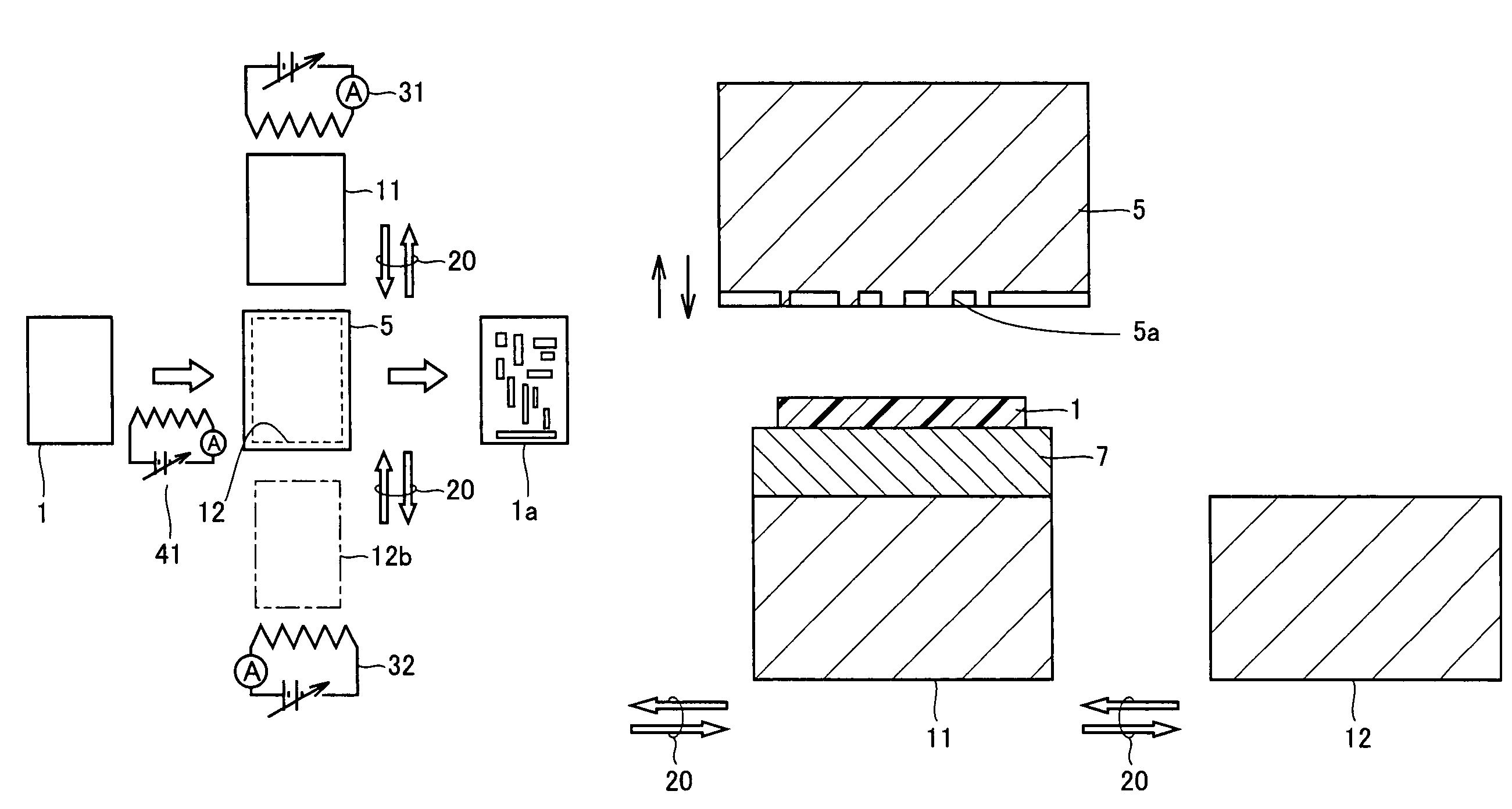
[0044]FIG. 1 is a top plan view showing an outline of a processing equipment of a fine structure according to a first embodiment of the present invention. Referring to FIG. 1, two movable opposed platens (hereinafter referred to as platens) 11 and 12 are arranged under a mold 5. In FIG. 1, cooling platen 12 is located on a molding / processing position immediately under mold 5, and heating platen 11 is located on a retreat position. Heating platen 11 is located on the molding / processing position when performing molding / processing by pressing the mold, and moves to the retreat position in cooling after the molding / processing. Cooling platen 12 is located on the molding / processing position when cooling molded / processed resin or the like before unmolding the same, and moves to a retreat position 12b when performing molding / processing by pressing mold 5 against a molded material 1 which is the resin. Referring to FIG. 1, reference numeral 20 denotes the direction of movement of platens 11...

second embodiment

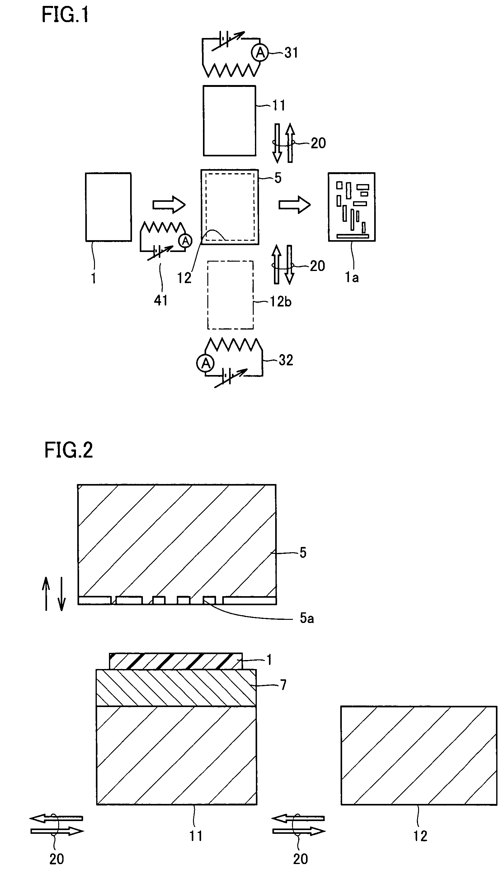
[0057]FIG. 2 is a sectional view showing an outline of a processing equipment of a fine structure according to a second embodiment of the present invention. Referring to FIG. 2, a platen 11 for a high temperature is arranged immediately under a mold 5, i.e., on a molding / processing position, while a platen 12 for cooling retreats to a retreat position. The feature of this embodiment resides in such a point that a base material 7 is arranged on platen 11, and a film 1 which is a molded material is arranged on this base material 7. Referring to FIG. 2, a mold section 5a is pressed against film 1 supported by base material 7 when film 1 is molded / processed with mold section 5a of mold 5. In this molding / processing, film 7 is heated by platen 11 along with base material 7.

[0058]Base material 7 is supported by a base material support mechanism (not shown), in order to continuously maintain the state of pressing the film against mold 5 also when platen 11 moves to the retreat position aft...

third embodiment

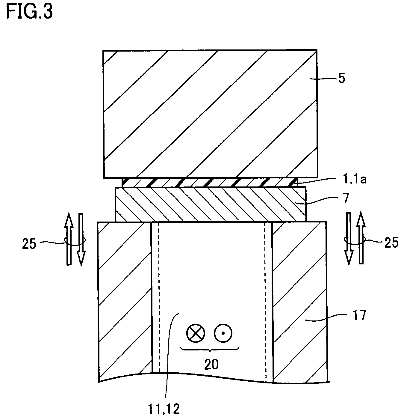
[0065]FIG. 3 is a partial sectional view of a processing equipment of a fine structure according to a third embodiment of the present invention. Referring to FIG. 3, a base material 7 is supported by a base material support mechanism 17 to maintain a state pressing a film 1 against a mold 5 while a platen 12 is arranged on a molding / processing position when a platen 11 moves to a retreat position after molding / processing. Base material support mechanism 17 is constituted of a post or a thick plate reciprocative in a direction 25. Base material support mechanism 17, coming into contact with base material 7 along with platens 11 and 12, is so provided as not to overlap with platens 11 and 12 arranged on the molding / processing position.

[0066]With the aforementioned base material support mechanism 17, relative positions of the mold and a molded material can be maintained, and a precise fine structure can be processed.

[0067]The basic element of the processing equipment of fine structure ...


PUM

PropertyMeasurementUnit
Raaaaaaaaaaa
temperatureaaaaaaaaaa
thicknessaaaaaaaaaa

Abstract

In a processing method of a fine structure according to the present invention, an opposed platen (211) is moved from a retreat position to a molding / processing position, so that a film (1) is pressed against a mold (5) and processed. Thereafter a second block (211b) is separated from a first block (211a). Thus, improvement of the cooling rate for the opposed platen (211) can be attained by reducing the total thermal capacity of the opposed platen (211) by reducing the volume of the opposed platen (211) in cooling and physically discharging heat stored in the opposed platen (211). Thus, cooling efficiency for the opposed platen (211) is improved, and the heat cycle of the opposed platen (211) can be reduced.

Description

RELATED APPLICATIONS[0001]This application is the U.S. National Phase under 35 U.S.C. §371 of International Application No. PCT / JP2006 / 303016, filed on Feb. 21, 2006, which in turn claims the benefit of Japanese Application No. 2005-050829, filed on Feb. 25, 2005 and Japanese Application No. 2005-132561, filed on Apr. 28, 2005, the disclosures of which Applications are incorporated by reference herein.TECHNICAL FIELD[0002]The present invention relates to a processing method of a fine structure employed for pattern formation of various devices integrated in the electronics field or the bio field and an processing equipment for the fine structure.BACKGROUND ART[0003]A semiconductor integrated circuit, various recording mediums, a biochip and the like are stationarily in the process of refinement and integration, and mask patterns or the like employed for manufacturing the same are also increasingly refined and integrated. After electron pattern exposure means has partially substituted...

Claims


Application Information

Patent Timeline
Patent Type & Authority Patents(United States)
IPC IPC(8): B29C51/42B29C59/00B81C99/00
CPCB29C43/021B81C1/0046B29C59/02B29C43/52B29C33/02B29C33/306B29C35/02B29C35/16B29C43/04B29C2043/025B29C2043/046B29C2059/023B81B2201/058
Inventor YORITA, JUNMIKAGE, KATSUNARI
Owner SUMITOMO ELECTRIC IND LTD
Why Eureka
Try Eureka