Laser irradiation apparatus

a laser light irradiation and apparatus technology, applied in the field of laser light irradiation apparatus, can solve the problems of difficult to balance laser light control with the control of laser light irradiation atmosphere, difficult to perform laser irradiation under controlled laser light irradiation atmosphere, etc., to achieve the effect of reducing the amount of gas flown before laser irradiation, simplifying the measurement of laser light irradiation conditions, and reducing the total amount of gas

Inactive Publication Date: 2010-05-11
SEMICON ENERGY LAB CO LTD
View PDF127 Cites 27 Cited by
  • Summary
  • Abstract
  • Description
  • Claims
  • Application Information

AI Technical Summary

Benefits of technology

[0013]It is an object of the present invention to perform laser irradiation under optimum conditions by making the operations simpler than conventional operations of checking the state of laser light.
[0024]Since a smaller plate is used in a laser irradiation apparatus of the invention as compared to that of a conventional one. Unlike a conventional irradiation apparatus, measurement can be conducted without removing the plate from the irradiation apparatus while being exposed to the atmosphere when a measurement apparatus is arranged under an optical. In other words, measurement of conditions of laser light irradiation can be simplified compared to a conventional laser irradiation apparatus. Therefore, time involved in measurement of laser light can be reduced. Further, since the space occupied by the interior of the plate is made smaller, the total amount of gas flown before laser irradiation can be reduced and the time of flowing gas before laser irradiation can be reduced. In addition, by using the laser irradiation apparatus of the invention, laser irradiation can be performed under a stable laser irradiation atmosphere; accordingly, variations in characteristics of TFTs can be reduced, and the characteristics of the TFTs can be improved.
[0025]In addition, when a laser irradiation apparatus of the invention is used, an expensive chamber which can withstand high pressure is not necessarily used, so that reduction in cost of an apparatus can be achieved.

Problems solved by technology

However, since the size of a plate for issuing gas used for a conventional laser irradiation apparatus is large, when a measuring probe or a measurement apparatus is placed between a substrate and an optical system through which a laser light lastly passes through, the plate needed to be removed while being exposed to the atmosphere.
In addition, the measurement system and the plate for issuing gas interfere with each other, and it has been difficult to balance laser light control with control of laser light irradiation atmosphere.
In other words, there have been many operations of checking the state of laser light, and further the arrangement conditions of the plate should have been changed, it has not been easy to perform laser irradiation under controlled laser light irradiation atmosphere.
In addition, the size of the plate is large, the total amount of gas flown for stabilizing the interior space of the plate before irradiation with laser light has been large.

Method used


Image

  • Laser irradiation apparatus
  • Laser irradiation apparatus
  • Laser irradiation apparatus

Examples


embodiment modes

[0058]Embodiment Modes of the present invention will be described in detail with reference to the drawings. It is to be noted that the present invention is not limited to the following description, and it is easily understood by those skilled in the art that modes and details thereof can be modified in various ways without departing from the sprit and the scope of the invention. Therefore, the present invention should not be construed as being limited to the description of the embodiment modes to be given below. Further, in a structure of the present invention, which will be described below, the same reference numerals are used for the same portions or portions having the same functions in different drawings.

embodiment mode 1

[0059]Embodiment Mode 1 of the present invention will be described with reference to FIG. 1 and FIG. 2.

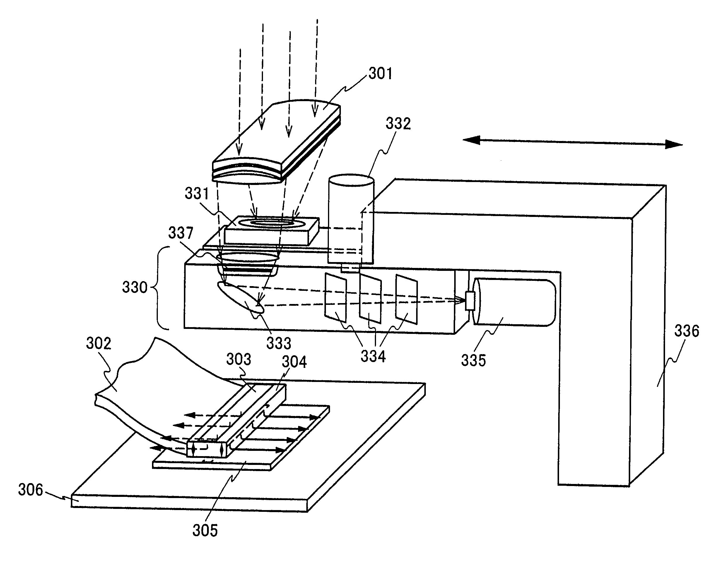
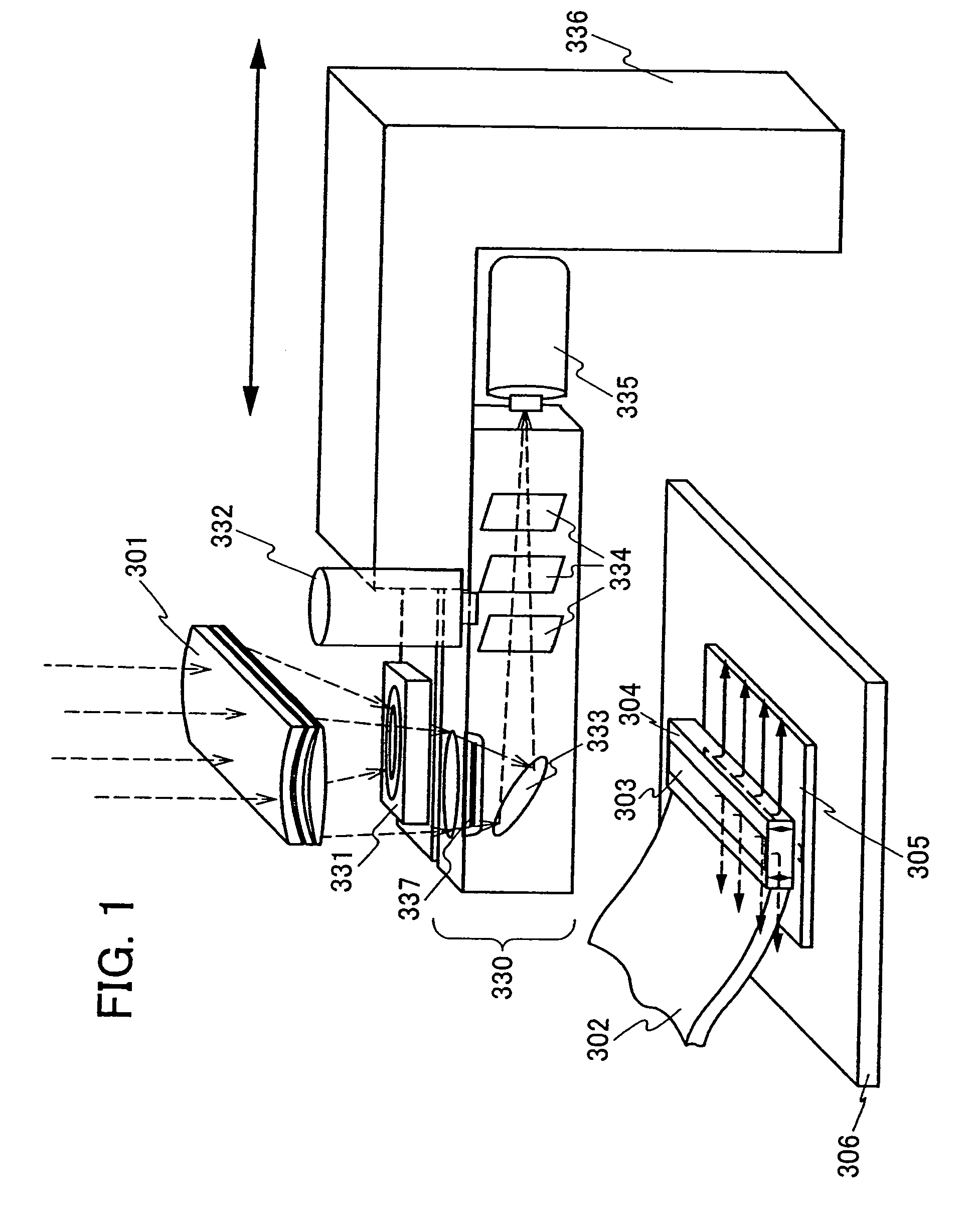
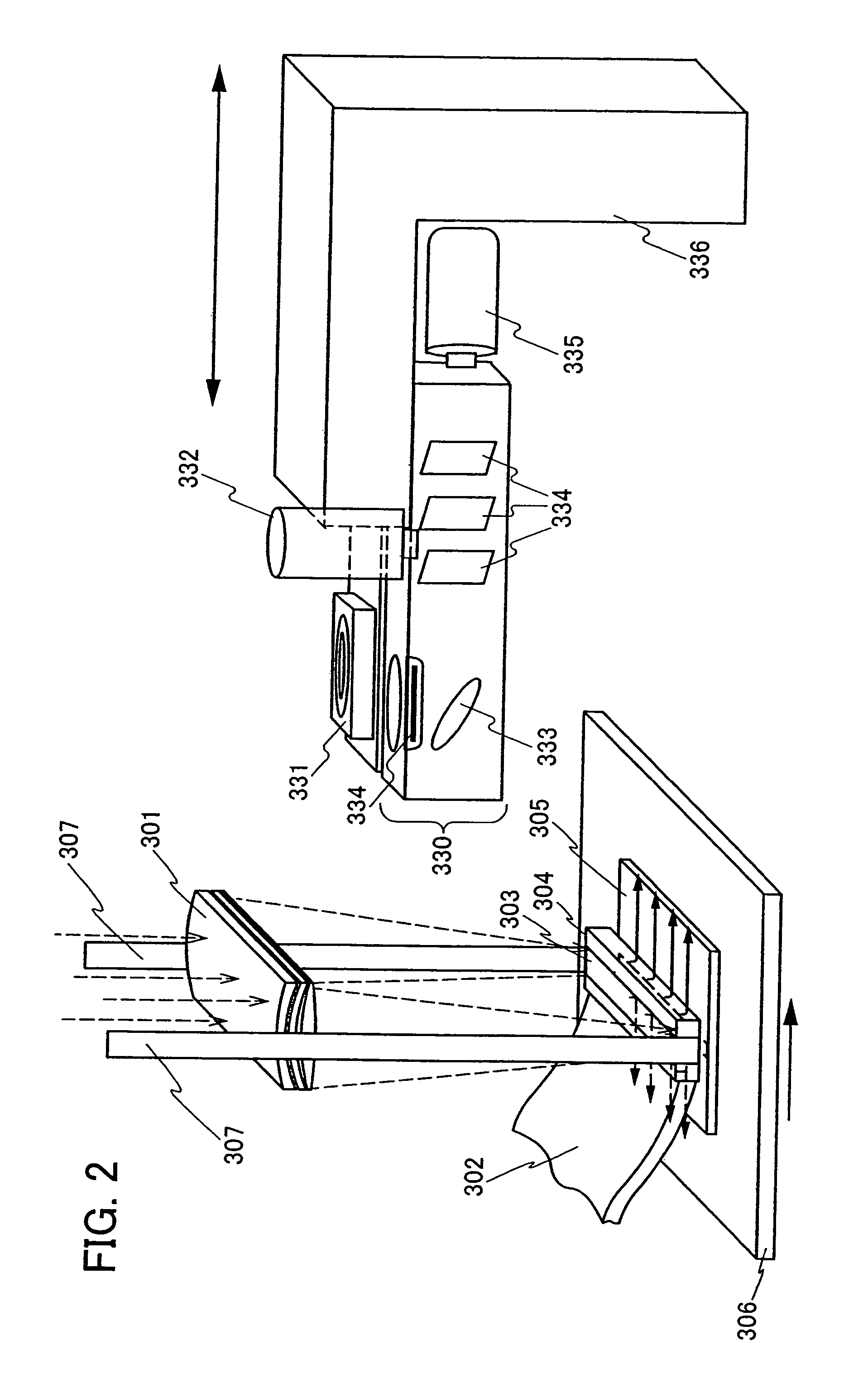
[0060]FIG. 1 and FIG. 2 each show an example of a laser irradiation apparatus of the invention. It is a feature that an irradiation apparatus of this embodiment mode includes a laser oscillator (not shown) for oscillating laser; an optical system for shaping a laser light, a plate for issuing gas onto a substrate surface; and a unit making it possible to monitor shape, the focal point, and energy of a laser light, which is provided between the optical system and the plate.

[0061]As a device making it possible to monitor shape, the focal point, and energy of a laser light, specifically, a power meter 331 measuring energy of laser light focused through an optical system and a beam profiler 330 used for checking the focal point and the shape of the focused laser light. In addition, the power meter 331 and the beam profiler 330 are held by the fixture 336. Optical systems other than a t...

embodiment mode 2

[0071]In this embodiment mode, an example of the structure of a plate for issuing gas will be described with reference to FIGS. 3A and 3B.

[0072]FIG. 3A shows an example of a plate for spray gas. A gas is supplied from a gas supply pipe 309 to the plate formed from a quartz window 310 and an aluminum alloy 311, and the gas is issued from a slit like hole provided at the bottom of the aluminum alloy. In this state, the plate is disposed immediately above a semiconductor film 312, and the distance between the plate and the semiconductor film is fixed at a certain length. Note that the plate may be floated bay the pressure of the issued gas. Note that although not shown in FIG. 3A, a supporting mechanism for stabilizing the position of the plate as the supporting mechanism 307 shown in FIG. 2 is necessarily provided. Using such a mechanism, the distance between the plate and the semiconductor film 312 can be fixed in a stable state. As shown as an example in the figure, a triplet cylind...


PUM

PropertyMeasurementUnit
thicknessaaaaaaaaaa
thicknessaaaaaaaaaa
wave lengthaaaaaaaaaa

Abstract

Since the size of a plate for issuing gas used for a conventional laser irradiation apparatus is large and the distance between an optical system through which a laser light lastly passes and the plate is not enough, it is difficult to check the state of laser light delivered from the optical system which the laser light lastly passes through. A laser irradiation apparatus includes a laser oscillator, an optical system shaping laser light produced by the laser oscillator, a plate having an opening for issuing a gas, a stage provided below the blower, means for maintaining a constant distance between the blower and the stage above the stage, and means provided between the optical system and the blower for observing the laser light transmitted through the optical system are provided.

Description

BACKGROUND OF THE INVENTION[0001]1. Field of the Invention[0002]The present invention relates to a laser irradiation apparatus and a method of manufacturing a semiconductor device, including a step of crystallizing a semiconductor film with laser or strong light using a laser apparatus of the invention. The semiconductor apparatus refers to all of devices that can function by using semiconductor properties, for example, an electro-optical device such as a liquid crystal display device, an electric apparatus including an electro-optical device as its component, a light emitting device, and a device which receives / transmits data wirelessly, such as a wireless chip, a wireless IC, an RFID chip, an IC chip, or an IC tag.[0003]2. Description of the Related Art[0004]A technology is widely studied whereby laser irradiation is performed on a semiconductor film formed over an insulating substrate, for the crystallization, the improvement of crystalline characteristics, and / or the activation ...

Claims


Application Information

Patent Timeline
Patent Type & Authority Patents(United States)
IPC IPC(8): B23K26/04H01L21/268
CPCB23K26/032B23K26/073B23K26/1405B23K26/426H01L27/1285H01L27/1266H01L27/13B23K26/142B23K26/705G02F1/13
Inventor MIYAIRI, HIDEKAZU
Owner SEMICON ENERGY LAB CO LTD
Why Eureka
Try Eureka