Control electronics for brushless motors

a technology of control electronics and motors, applied in the direction of electronic commutators, motor/generator/converter stoppers, dynamo-electric converter control, etc., can solve the problems of assembly costs, the disadvantage of hall sensors, etc., and achieve the effect of improving electric efficiency

Inactive Publication Date: 2010-05-11
THOR POWER
View PDF11 Cites 16 Cited by
  • Summary
  • Abstract
  • Description
  • Claims
  • Application Information

AI Technical Summary

Benefits of technology

[0008]The preferred embodiments provide improved electric efficiency compared to conventional alternating current motor systems. The application of the preferred embodiments are almost limitless, as alternating current motors are used extensively, world-wide, today in many products and applications, including air conditioners, refrigerators, power tools, washers, and dryers, and industrial power tools, such as angle grinders, to name a few. The preferred embodiments use new electronic motor control circuitry, which may be combined with highly efficient rare-earth magnetic, brushless direct current (BLDC) motors, to electronically regulate the motor.
[0009]Some embodiments may accept all major international voltages, eliminating the need for having different control electronics and motors for many different countries. These embodiments may be applied to motor systems up to 5 kilowatts, but have particular application to the 1 to 2 kilowatt power range.
[0014]Implement a PFC circuit design that is highly compact (smaller choke and power semiconductor devices and high efficiency). This is achieved through: a) very low Rds(on) MOSFETs (but still commercially viable); b) state-of-art Silicon Carbine Diode (SIC Diode) for zero reverse recovery current; c) higher switching frequency (over 60 kHz), even under 110V supply, over 50 A current; and d) high switching frequency enabling much reduced choke size.
[0015]An inverter uses an IGBT IPM module with specific thermal substrate and package design. Through motor control algorithm, full advantage is taken of the IGBT characteristics, and the inverter achieves very compact design and high efficiency.

Problems solved by technology

This method has the disadvantage of fitting the hall sensors (including components and assembly costs).

Method used


Image

  • Control electronics for brushless motors
  • Control electronics for brushless motors
  • Control electronics for brushless motors

Examples


Embodiment Construction

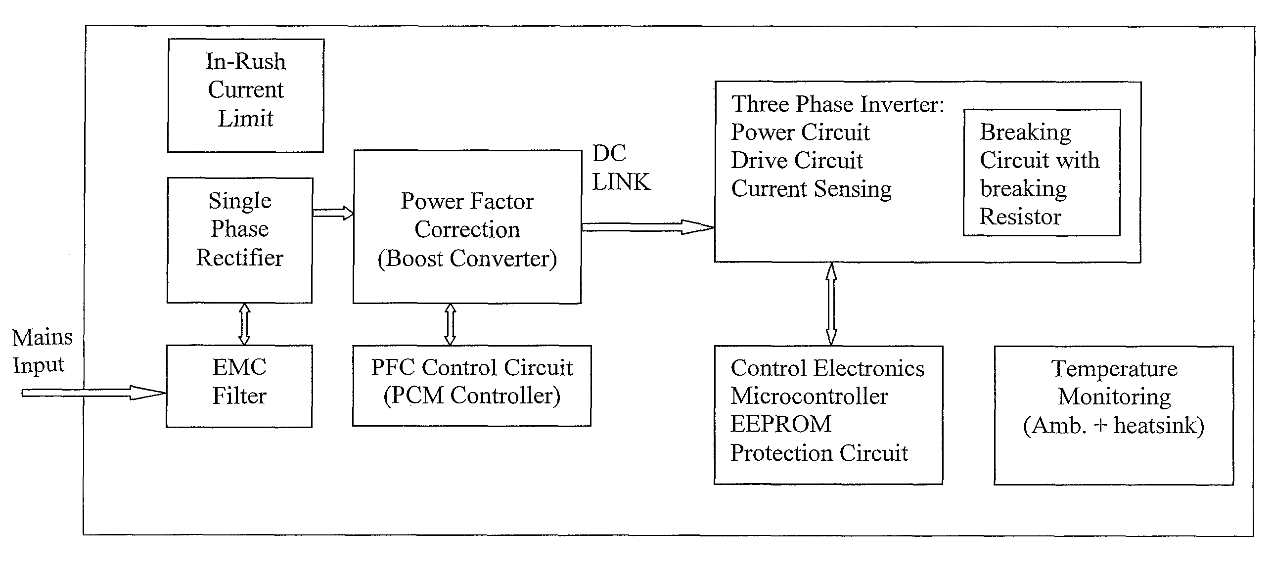
[0023]The preferred embodiments are directed to control electronics for brushless dc motors. The major building blocks are described below. Where specifics are provided, such as the identification of suitable parts, such specifics are illustrative and exemplary, and need not be utilized in a particular preferred embodiment. While the preferred embodiments have a power rating of about 2 kilowatts, with overload capability, and work with both European (230V AC) and American (110V AC) supply voltages, they may be applied or adapted for motors up to about 5 kilowatts or with different supply voltage capabilities.

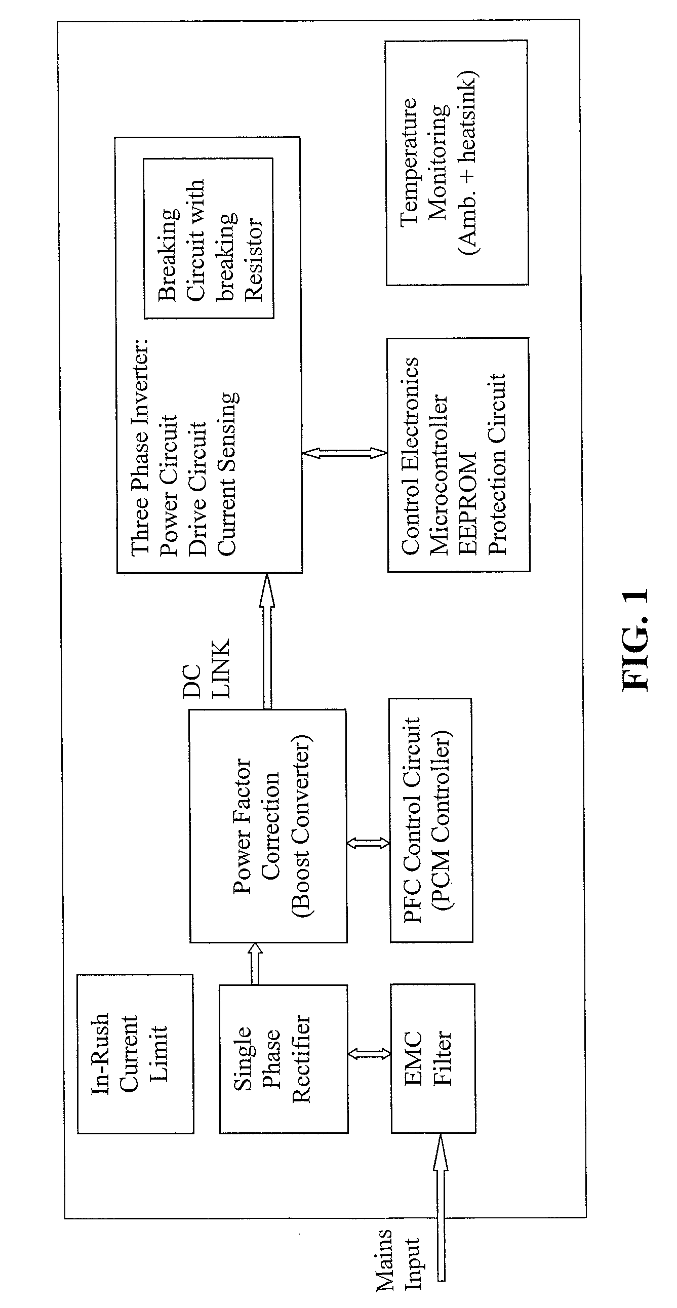
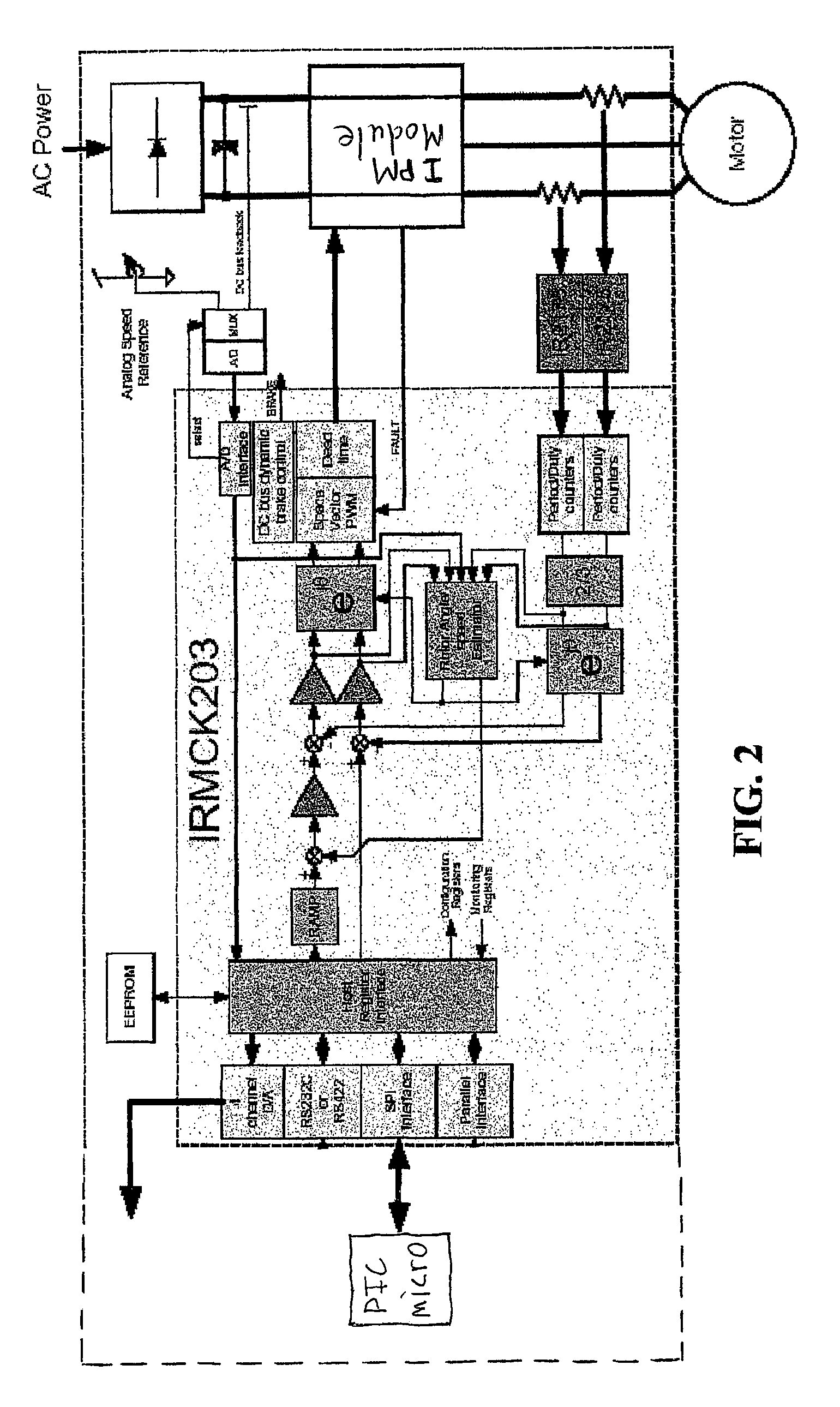
[0024]A block diagram of the control electronics is shown in FIG. 1. Optimally, the electronics are separated and divided into two parts on a single printed circuit board. On the left side, there is input power control circuitry connected by a DC link to control circuitry on the right side.

[0025]The input power control circuitry receives the main input and includes an EMC filter...


PUM


Abstract

An electronic control circuit controls a brushless DC motor. It includes an input power supply control circuit. A microcontroller integrated circuit has control functions to control a brushless DC motor. Additional control functions are provided by software program instructions, which when executed, cause the microcontroller integrated circuit to perform additional control functions for the brushless DC motor.

Description

RELATED APPLICATIONS[0001]This application claims priority to U.S. Provisional Patent Application Ser. No. 60 / 712,945, filed Aug. 31, 2005 and to U.S. Provisional Patent Application Ser. No. 60 / 725,775, filed Oct. 11, 2005. The contents of both provisional applications are hereby incorporated by reference in their entirety.FIELD OF THE INVENTION[0002]The invention relates generally to power electronics. In particular, the invention relates to control electronics for brushless motors.BACKGROUND OF THE INVENTION[0003]The US Department of Energy estimates that alternating current motors consume more than 65% of the electricity produced today and total electricity sales in the US will increase at an average annual rate of 1.9%, from 3,481 billion kilowatt hours in 2001 to 5,220 billion kilowatt hours in 2025. With a reduction in electrical energy consumption by 33%, by today's measure, is equivalent to the total output of 840 fossil fuel-based power plants. Throughout the world, electri...

Claims


Application Information

Patent Timeline
Patent Type & Authority Patents(United States)
IPC IPC(8): H02P7/06
CPCH02P23/0077H02P27/06H02P21/0035H02P21/22
Inventor BONNER, DAVIDXU, AIDONG
Owner THOR POWER
Why Eureka
Try Eureka