Light emitting device using light emitting diode chip

a technology of light-emitting diodes and light-emitting diodes, which is applied in the direction of discharge tube luminescnet screens, free standing, lighting and heating apparatus, etc., can solve the problems of uneven color between the central area, difficult control of resin drop amount, and inability to increase productivity, so as to reduce the difference in the length of light paths, improve light efficiency, and high elasticity

Active Publication Date: 2010-05-18
MATSUSHITA ELECTRIC WORKS LTD
View PDF29 Cites 73 Cited by
  • Summary
  • Abstract
  • Description
  • Claims
  • Application Information

AI Technical Summary

Benefits of technology

[0017]In view of the above problems, a first object of the present invention is to provide a light emitting device using a wavelength converting member that is excited by light emitted from a light emitting element mounted in a recess formed in a mounting substrate so as to emit light of a wavelength different from the excitation wavelength, wherein light that is emitted from the edge area of the wavelength converting member outside the recess of the mounting substrate and that has a color different from that of light emitted from the central area of the wavelength converting member can be prevented from being directed to the irradiation surface of the device, so that unevenness of color can be reduced on the irradiation surface.
[0018]A second object of the present invention is to, in a light emitting device comprising a lens for controlling emission of light coming from a wavelength converting member, reduce the mounting surface area of a wiring board that is occupied by a lens holder so that an electronic component can be disposed adjacent to a mounting substrate, and thus the wiring board can be made compact to reduce the size of the device.
[0019]A third object of the present invention is to in light emitting devices comprising a light extraction increasing portion, reduce variations in the effects of the light extraction increasing portions and thus reduce variations in the light outputs or the light emitting devices by setting the height of sealing resin in a recess of a mounting substrate, where an LED chip is mounted, near the upper end of the recess of the mounting substrate.

Problems solved by technology

However, the above technique has the problems that the process is complex and further, it is difficult to control the amount of resin dropped.
However, as a result of detailed studies of light emitting devices having the above described structure, the inventors of this application have found that there is a problem in the case where such a light emitting device is one using the principle that visible light emitted from the LED chip 1 is converted by the wavelength converting member 5 into visible light within a wavelength hand different from that of the light emitted from the LED chip so that the visible light emitted from the LED chip 1 is mixed with the visible light produced by the wavelength converting member 5.
A major possible cause of the above problem is that light emitted from the LED chip 1 cannot directly enter the edge area of the wavelength converting member 5 that is around the recess 2a of the mounting substrate 2 because the light is blocked by the recess 2a.
This may cause the unevenness of color between the central area and the edge area of the wavelength converting member 5.
However, in fact, the above way has the problem that the productivity cannot be increased with difficulty in automatic assembling due to dimensional tolerances of the recess 2a and the wavelength converting member and further due to tolerances in placing the wavelength converting member within the recess 2a.
Accordingly, the optical axis A of the LED may be misaligned with respect to the optical axis B of the hybrid lens, thus causing the above described problem.
There is a difficulty for controlling the amount of sealing resin 19 dropped.
Accordingly there is a problem that the height of sealing resin 19 covering the bottom part of the light extraction increasing portion 15 cannot be made uniform, and as a result, variations may occur in the light extraction increasing effects of light extraction increasing portions 15 and then in the light outputs of light emitting devices.

Method used


Image

  • Light emitting device using light emitting diode chip
  • Light emitting device using light emitting diode chip
  • Light emitting device using light emitting diode chip

Examples


first embodiment

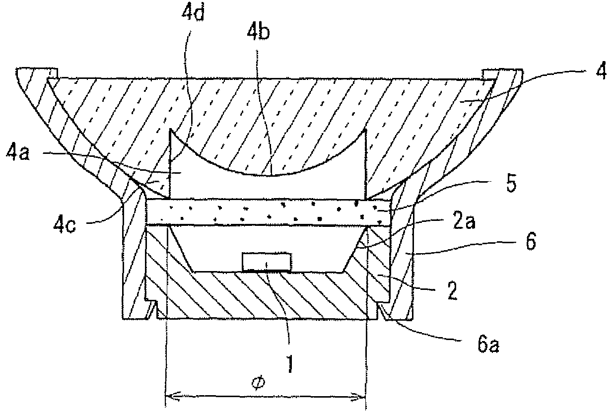
[0056]FIG. 1 shows the schematic configuration of a light emitting device according to a first embodiment. This light emitting device comprises: an LED chip 1: a mounting substrate 2 having a recess 2a in which the LED chip 1 is mounted; a sheet-like wavelength converting member 5 disposed so as to cover the recess 2a and the area around the recess; and a hybrid lens 4 provided at the light output side of the wavelength converting member 5 to function as an emission control member that allows light coming from an area of the wavelength converting member corresponding to the recess 2a to be emitted therefrom. The LED chip 1 is mounted on the bottom of the recess 2a in the mounting substrate 2. The recess 2a has a circular cross section and has a tapered wall. The hybrid lens 4 as the emission control member is provided for preventing uneven color from appearing due to the difference in color between light emitted from the central area of the wavelength converting, member 5 and light ...

second embodiment

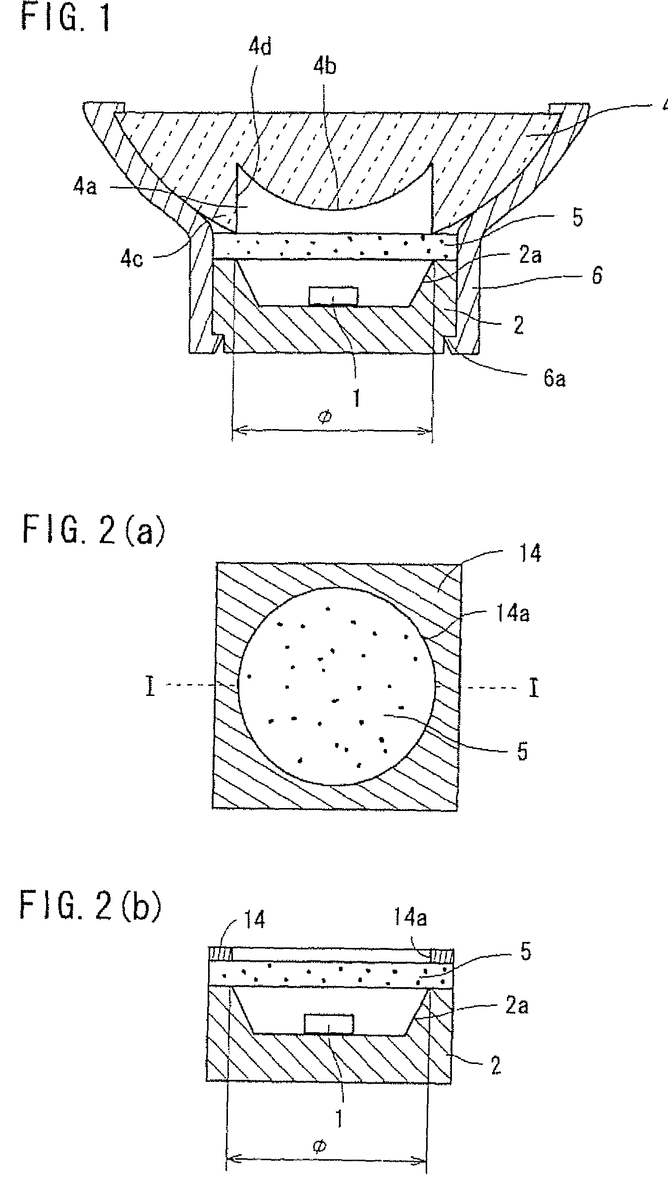
[0062]FIGS. 2(a) and 2(b) show the schematic configuration of a light emitting device according to a second embodiment. In place of the optical member as the emission control member used in the above described light emitting device according to the first embodiment, this light emitting device has a frame member 14 made of a light blocking material at the light output side of a wavelength converting member 5. The other components are configured similar to those in the first embodiment. The frame member 14 has an opening 14a corresponding to the recess 2a. The end of the opening 14a has substantially the same shape (diameter φ) as the open end of the recess 2a. This embodiment also achieves an effect equivalent to that of the above embodiment. More particularly, in this embodiment, light emitted from the edge area of the wavelength converting member 5 can be blocked for prevention of unevenness of color.

third embodiment

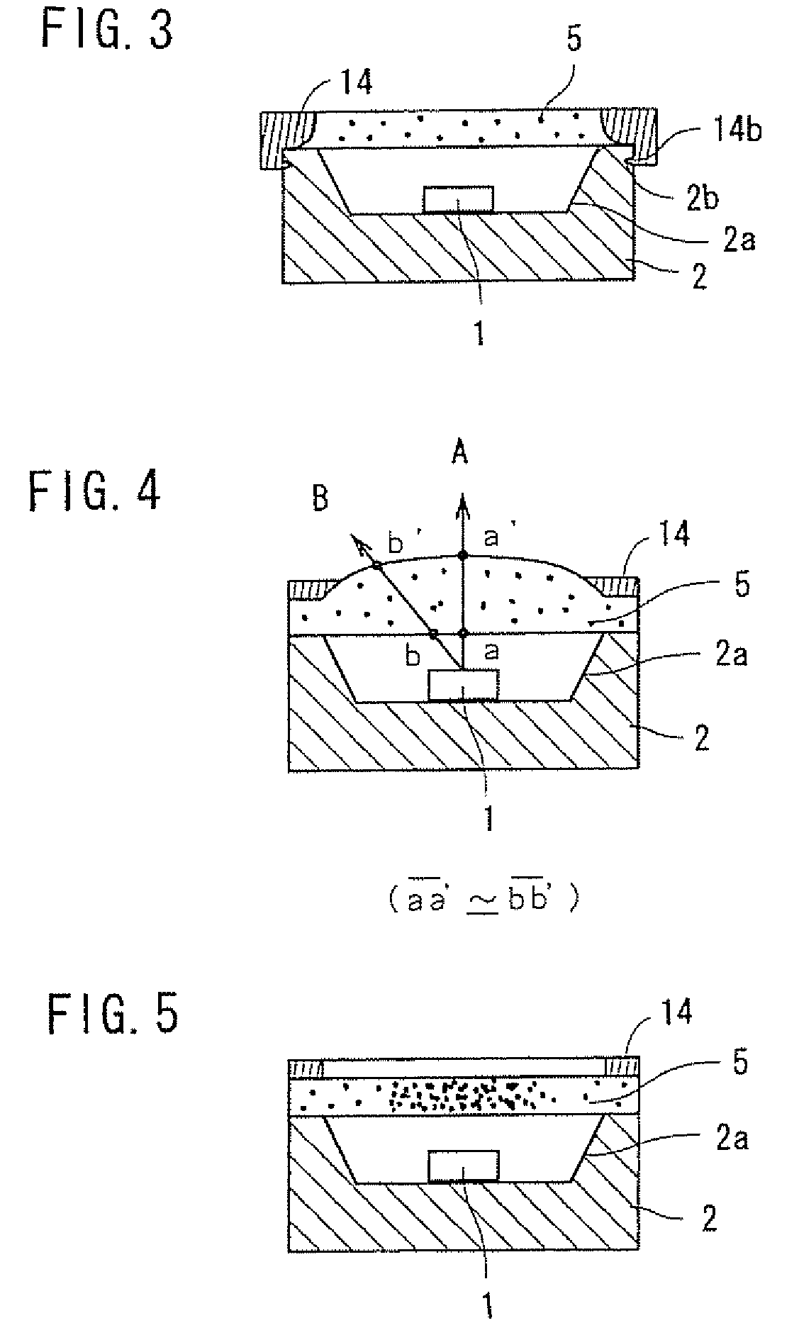
[0063]FIG. 3 shows the schematic configuration of a light emitting device according to a third embodiment. This light emitting device is configured similar to the second embodiment except that it uses a wavelength converting member 5 with high elasticity. More particularly, silicone resin with high elasticity is used as the light transmissive material. A frame member 14 is pressed against the wavelength converting member 5, whereby part of the wavelength converting member 5 that is located on the edge area around the recess 2a is compressed. The frame member 14 pressing the wavelength converting member 5 is fixed to a mounting substrate 2 with a claws 14b, which is formed at the under side of the frame member 14, being engaged in a groove 2b formed in the side face of the mounting substrate 2.

[0064]This embodiment not only achieves the above described effect but also makes it hard for light within the wavelength converting member 5 to be propagated to the area of the member 5 that i...


PUM


Abstract

A light emitting device comprises: an LED chip mounted in a recess formed in a mounting substrate; a wavelength converting member that is disposed so as to cover the recess and the edge area around the recess and that is excited by light emitted from the LED chip to emit light of a wavelength different from an excitation wavelength; and an emission control member disposed at a light output side of the wavelength converting member so as to allow emission of light coming from an area of the wavelength converting member that corresponds to the recess and to prevent emission of light coming from an area of the wavelength converting member that corresponds to the edge area around the recess. This can prevent variations in color between light emitted from the central part of the wavelength converting member and light emitted from the part of the wavelength converting member that is located on the edge area around the recess of the mounting substrate, thereby reducing unevenness of color on the irradiation surface.

Description

TECHNICAL FIELD[0001]The present invention relates to a light emitting device that has a light emitting diode (LED) as a light source so as to be used for illumination, indication, or the like.BACKGROUND ART[0002]In these years, LED chips have been developed that emit blue light or ultraviolet light by a gallium nitride compound semiconductor. By combining such LED chips with various wavelength converting materials such as fluorescent pigment and fluorescent dye, attempts are being made to develop LED light-emitting devices that produce light of while or other color different from the color of light emitted from the chip. The LED light-emitting devices have the advantages of being compact and lightweight, and requiring relatively less power, and are currently in wide use as indication lights, alternatives to small light bulbs, light sources for liquid crystal panels, and so on. A general method for fixing a wavelength converting material in the above LED light-emitting devices is to...

Claims


Application Information

Patent Timeline
Patent Type & Authority Patents(United States)
IPC IPC(8): F21V9/00F21V9/16H01J1/62H01L33/50H01L33/58H01L33/60
CPCH01L33/507H01L33/58H01L33/60H01L33/508H01L2924/3025Y10S362/80H01L2224/73265H01L2224/48247H01L2224/32245H01L2924/00H01L2224/48091H01L2924/16195H01L2924/00014
Inventor NISHIOKA, KOUJISUGIMOTO, MASARUKIMURA, HIDEYOSHIYOKOTANI, RYOJIIWAHORI, YUTAKAHASHMOTO, TAKUMAISHIZAKI, SHINYAMORI, SATOSHISEKII, HIROYUKISHIOHAMA, EIJI
Owner MATSUSHITA ELECTRIC WORKS LTD
Why Eureka
Try Eureka