System and method for managing power deactivation within a medical imaging system

a technology of medical imaging and power deactivation, applied in the field of imaging systems, can solve the problems of affecting the operation of the control unit, so as to reduce the power supply

Active Publication Date: 2010-05-18
GENERAL ELECTRIC CO
View PDF9 Cites 130 Cited by
  • Summary
  • Abstract
  • Description
  • Claims
  • Application Information

AI Technical Summary

Benefits of technology

[0014]Certain embodiments of the present invention also provide a method of deactivating a fluoroscopic imaging system, which may be a portable x-ray system that runs on battery power. The fluoroscopic imaging system may include a (i) C-arm assembly having a C-shaped body with an x-ray source and a detector mounted thereto and a C-arm operation control unit configured to control movement of the C-shaped body, and (ii) a fluoroscopic imaging control subsystem having an imaging control unit in communication a monitor and the C-arm assembly. The method includes operatively connecting an activation unit to the C-arm assembly and the fluoroscopic imaging control subsystem, engaging the activation unit into a deactivation position, and deactivating both the C-arm assembly and the fluoroscopic imaging control subsystem through the engaging step. The deactivating step includes (i) immediately powering off the C-arm assembly and (ii) reducing power supplied to the fluoroscopic imaging control subsystem for a set period of time.

Problems solved by technology

Deactivating the control unit abruptly poses several risks.
An abrupt deactivation may preclude application software within the control unit from completing a particular task(s), and damage the hard drive.
Additionally, separate power / reset switches for multiple components within a system may lead to confusion, and may cause an operator to engage a wrong switch.

Method used


Image

  • System and method for managing power deactivation within a medical imaging system
  • System and method for managing power deactivation within a medical imaging system
  • System and method for managing power deactivation within a medical imaging system

Examples


Embodiment Construction

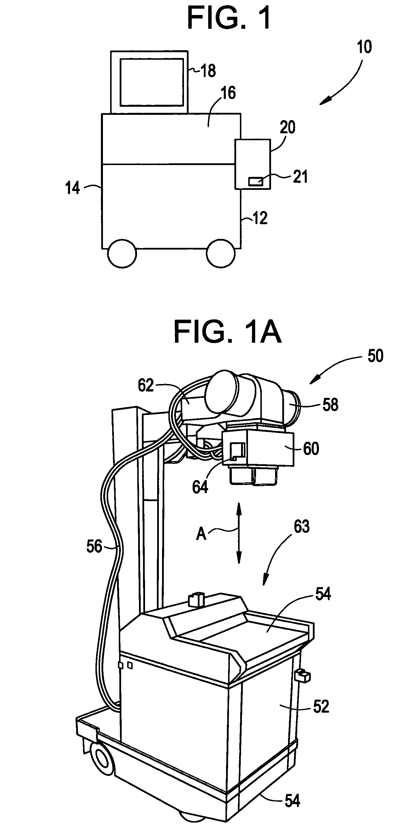
[0020]FIG. 1 illustrates a medical imaging system 10 according to an embodiment of the present invention. The imaging control system 10 includes a main body 12 housing an imaging control unit or central processing unit 14, electronics, and other components, a user control input unit 16 (such as a keyboard, mouse, or touchscreen monitor), an imaging device (such as portable fluoroscopic imaging device, an x-ray C-arm, ultrasound probe, or the like), a display unit 18, and an activation unit 20. The user control input unit 16, the imaging equipment (such as a fluoroscopic, ultrasound, or other such imaging system), the display unit 18 and the activation unit 20 are each in operative electrical communication with the central processing unit 14.

[0021]The activation unit 20 is in electrical communication with each component of the medical imaging system 10. For example, the activation unit 20 is in electrical communication with power control processing circuits of each of the display uni...


PUM


Abstract

A medical imaging system includes a medical imaging device, a medical imaging control subsystem, and an activation unit. The medical imaging control subsystem includes a processing unit and a monitor. The processing unit is in communication with the medical imaging device and the monitor. The activation unit is operatively connected to the medical imaging device and the medical imaging control subsystem, wherein the activation unit is operable to deactivate the medical imaging device and the medical imaging control subsystem.

Description

RELATED APPLICATIONS[0001]This application relates to and claims priority benefits from U.S. Provisional Patent Application No. 60 / 673,026 entitled “System and Method for Managing Power Deactivation Within a Medical Imaging System,” filed Apr. 20, 2005, which is incorporated by reference herein in its entirety.BACKGROUND OF THE INVENTION[0002]Embodiments of the present invention generally relate to imaging systems, such as medical imaging systems, and more particularly to a system and method of managing power deactivation within a medical imaging system.[0003]Various medical imaging systems and modalities are known and used for diagnosis and assisting in treatment and surgery. For example, ultrasound, magnetic resonance (MR), computed tomography, fluoroscopy and other types of imaging modalities have been used to image various anatomical features.[0004]Various medical imaging systems include a master power device configured for switching a medical imaging system on and off. More par...

Claims


Application Information

Patent Timeline
Patent Type & Authority Patents(United States)
IPC IPC(8): A61B6/00H05G1/56
CPCA61B5/055A61B6/00H05G1/56A61B6/56A61B8/00A61B6/4405A61B6/4441A61B8/4405A61B2560/0214A61B6/467
Inventor OMERNICK, JON C.ZAMAN, SABIH QAMAR-UZ
Owner GENERAL ELECTRIC CO
Why Eureka
Try Eureka