Combustion control system for internal combustion engine

a combustion control and internal combustion engine technology, applied in the direction of electric control, ignition automatic control, machines/engines, etc., can solve the problems of difficulty similar to other conventional cases of conventional compression self-ignition combustion, difficulty in combustion control, and still unresolved problems, etc., to achieve optimal combustion

Inactive Publication Date: 2010-05-25
NISSAN MOTOR CO LTD
View PDF22 Cites 34 Cited by
  • Summary
  • Abstract
  • Description
  • Claims
  • Application Information

AI Technical Summary

Benefits of technology

[0007]In view of the problems described above, an object of the present invention is to compatibly accomplish a low fuel consumption cost and a high output when combustion is performed by distributing a plurality of fuels having different octane numbers from one another to different portions of a combustion chamber.
[0010]According to the present invention, switching between ignition start portions is performed corresponding to the engine operation condition. Consequently, combustion can be executed from a portion of fuel having an octane number suited for the operation condition, and hence optimal combustion can be implemented.

Problems solved by technology

Nevertheless, problems described below still remain unresolved.
On the other hand, however, from the viewpoint of controlling combustion, there is a difficulty similar to other conventional cases of conventional compression self-ignition combustion.
More specifically, when there is a change in operation conditions, and in particular, when the engine load is high, difficulties in combustion control are known.
More specifically, when control is performed only to start ignition with the ignition of the low octane fuel regardless of the engine load, it is difficult to compatibly accomplish high thermal efficiency and output in a wide range of operation conditions.

Method used


Image

  • Combustion control system for internal combustion engine
  • Combustion control system for internal combustion engine
  • Combustion control system for internal combustion engine

Examples


first embodiment

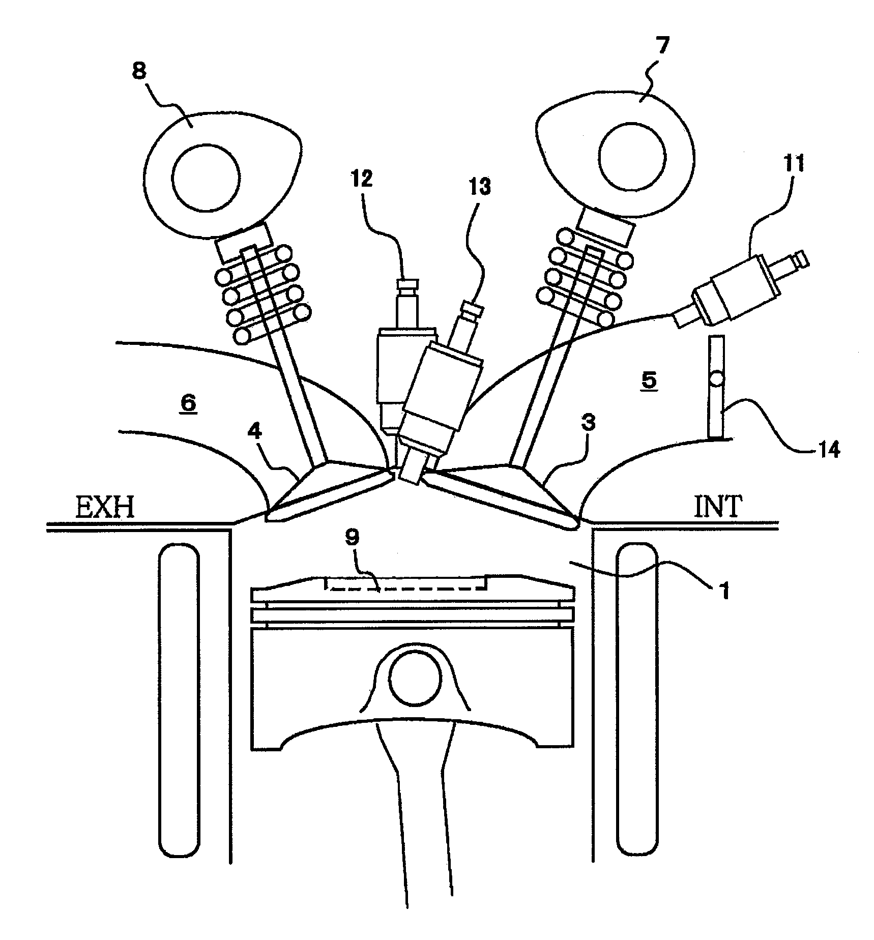
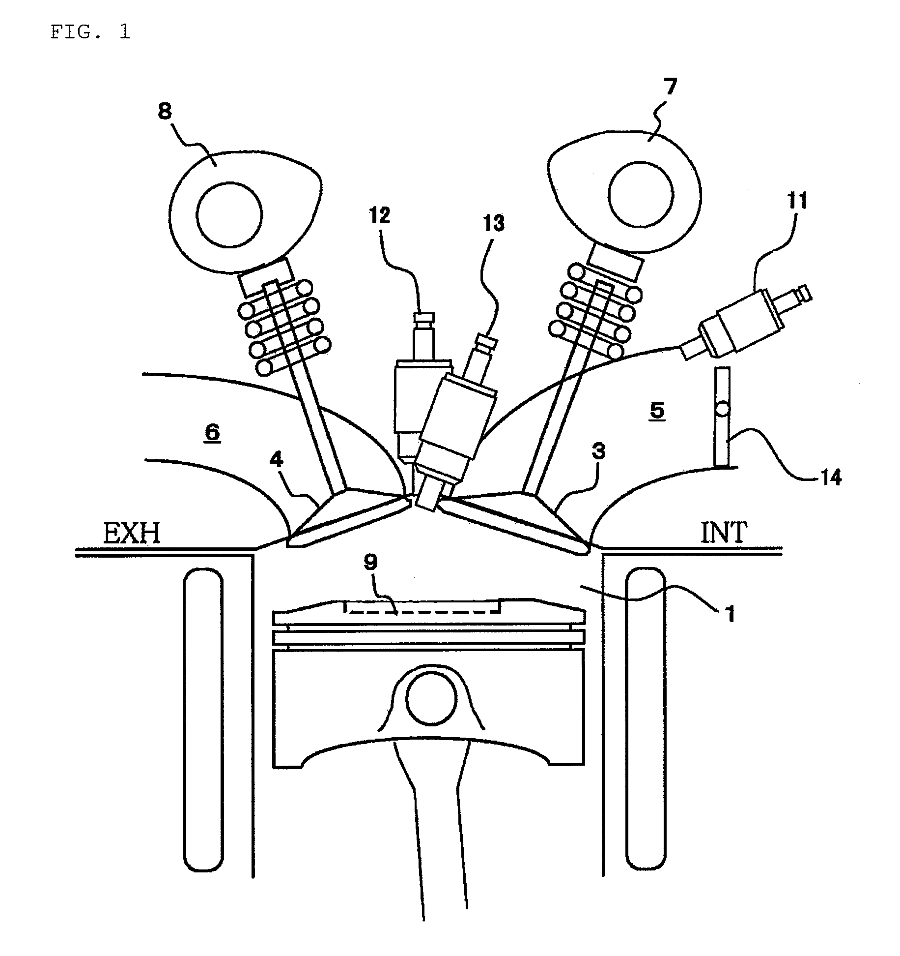
[0027]FIG. 1 is a diagram showing an internal combustion engine according to the present invention.

[0028]A combustion chamber 1, working as a main combustion chamber includes a cylinder head, a cylinder block and a piston. The combustion chamber 1 communicates with an intake port 5 and an exhaust port 6 via an intake valve 3 and an exhaust valve 4, respectively. The intake valve 3 and the exhaust valve 4 are opened and closed in operative association with an intake valve driving cam 7 and an exhaust valve driving cam 8, respectively. A cavity 9 or piston cavity is formed in a surface of a piston crown.

[0029]The intake port 5 is provided with a first fuel injection valve 11 for supplying a high octane fuel. A lower surface of the cylinder head includes a second fuel injection valve 12 for supplying a low octane fuel and a third fuel injection valve 13 that works as an ignition trigger device for supplying an initial ignition fuel.

[0030]The fuel to be sprayed from the first fuel injec...


PUM


Abstract

In an embodiment, the invention provides an internal combustion engine, including a first fuel injector that supplies a first fuel to a first predetermined region in a combustion chamber, and a second fuel injector that supplies a second fuel to a second predetermined region in the combustion chamber. The second fuel has an octane number that is different than an octane number of the first fuel, and the second predetermined region is different from the first predetermined region. An ignition device is configured to start ignition of one of the first and second fuels based on an ignition signal. An operation condition detector detects at least one engine operating condition. A controller is configured to provide the ignition signal to the ignition device and to determine which one of the first and second fuels to ignite by the ignition device based on the engine operation condition.

Description

CROSS-REFERENCE TO RELATED APPLICATIONS[0001]This application claims priority to Japanese Patent Application No. 2007-82799, filed Mar. 27, 2007, which is incorporated by reference herein in the entirety.BACKGROUND OF THE INVENTION[0002]1. Field of the Invention[0003]The present invention relates to a combustion control system for an internal combustion engine that uses a plurality of fuels having different octane numbers.[0004]2. Description of Related Art[0005]A related art combustion control system for an internal combustion engine includes fuel injection valves that, respectively, inject a low octane fuel and a high octane fuel into a combustion chamber. During the compression stroke, fuel injection is performed such that the low and high octane fuels substantially do not overlap one another in the combustion chamber. The concentration of the gaseous mixture in the combustion chamber is prevented from being over-concentrated, fuel distributions different in octane number can be ...

Claims


Application Information

Patent Timeline
Patent Type & Authority Patents(United States)
IPC IPC(8): F02M43/00F02B13/00
CPCF02B17/005F02D19/081F02B23/0663F02B23/101F02D15/00F02D41/0025F02D41/3011F02P15/02F02D19/0634F02D19/0649F02D19/0665F02D19/0671F02D19/0689F02D19/0692F02B19/12F02B2023/085F02B2023/102F02B2023/108F02B2075/125F02B2275/16F02D41/3029F02D2700/03F02M25/0723F02M2023/008F02P5/04Y02T10/125Y02T10/36Y02T10/123F02M26/20Y02T10/12Y02T10/30
Inventor KAKUHO, AKIHIKOARAKI, TAKASHIASHIDA, KOICHI
Owner NISSAN MOTOR CO LTD
Why Eureka
Try Eureka