
Method and apparatus for fast pulse harmonic fiber laser

a harmonic fiber laser and pulse-frequency conversion technology, applied in semiconductor lasers, optical resonators, instruments, etc., can solve the problems of narrow spectral linewidth, primary limitation, grating technology, and inability to provide efficient pulse compression for high average power light with narrow spectral linewidth, and achieve narrow optical bandwidth and high efficiency.

Inactive Publication Date: 2010-06-08
DEEP PHOTONICS CORP
View PDF9 Cites 30 Cited by
  • Summary
  • Abstract
  • Description
  • Claims
  • Application Information

AI Technical Summary

Benefits of technology

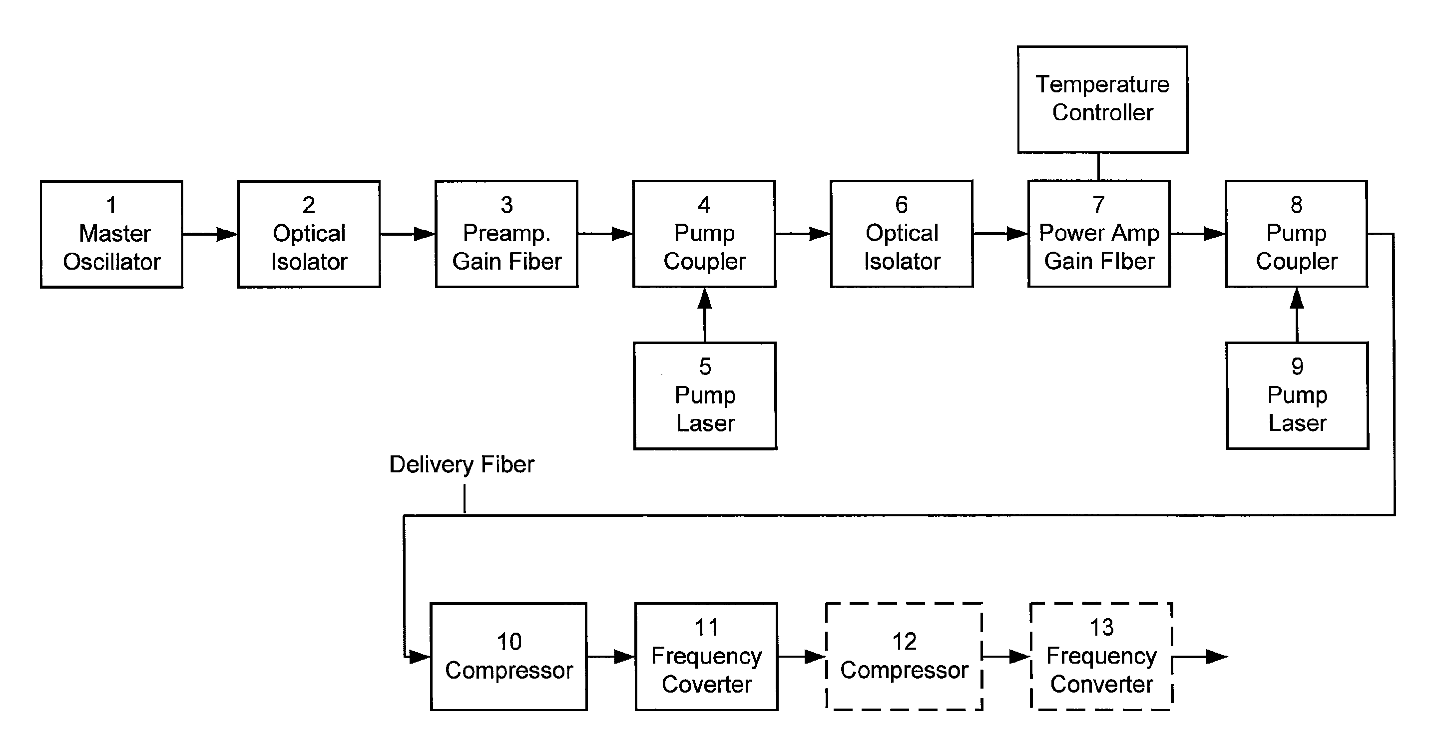
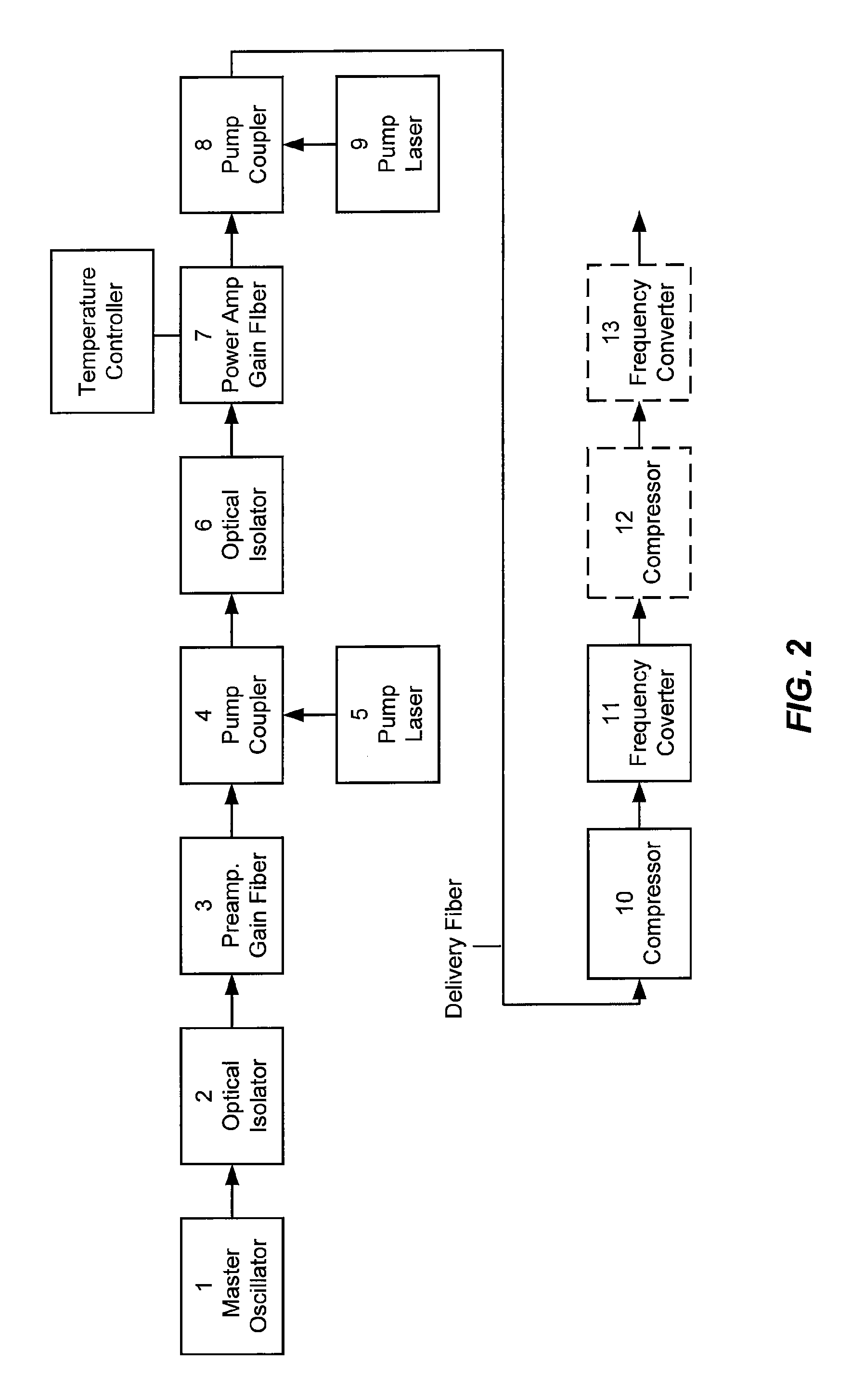
"The present invention is a fiber laser apparatus that can generate linearly-polarized laser radiation with peak powers of 5 kW to 1 MW and wavelengths of 508-542 nm. The apparatus has a unique design that allows for efficient pulse compression and high average power. The apparatus includes a master oscillator, a polarization-maintaining optical isolator, a fiber amplifier, a pulse compression stage, and a nonlinear frequency conversion stage. The apparatus can be used in various applications such as light detection and ranging (LIDAR) systems, laser-based micromachining systems, and laser-based microsystems. The apparatus has high efficiency, narrow spectral bandwidth, and a predominately single spatial mode. The technical effects of the invention include efficient and high-powered fiber laser pulses with narrow spectral linewidth and high repetition rates."

Problems solved by technology

Pulse compression means known in the art cannot simultaneously provide efficient pulse compression for high average power light with narrow spectral linewidth.
The primary limitation is grating technology.
Fiber Bragg gratings have not been used at high average power because of difficulty in coupling in and out of the fiber grating.
While the requirement for high efficiency can be accomplished by ruled surface transmission gratings, ruled surface gratings cannot be manufactured with the line density required in order to compress pulses with narrow spectral linewidth.

Method used


Image

  • Method and apparatus for fast pulse harmonic fiber laser
  • Method and apparatus for fast pulse harmonic fiber laser
  • Method and apparatus for fast pulse harmonic fiber laser

Examples


Embodiment Construction

[0019]Without limiting embodiments of the present invention, the following glossary is provided in relation to the description herein.

[0020]Chirped pulse: represents a temporal pulse of electromagnetic radiation in which the wavelength changes during the duration of the pulse.

[0021]Deep ultraviolet (DUV): A portion of the electromagnetic spectrum with wavelengths in the range of 100-315 nm.

[0022]Diode Laser: refers to a light-emitting diode designed to use stimulated emission to generate a coherent light output. Diode lasers are also known as laser diodes or semiconductor lasers.

[0023]Diode-Pumped Laser: refers to a laser having a gain medium that is pumped by a diode laser.

[0024]Double-clad Fiber: An optical fiber that contains a core region that guides a first light signal, surrounded by a first cladding region that contains the first light signal within the core. The first cladding region also guides a second light signal. The first cladding region is surrounded by a second cladd...


PUM


Abstract

A fiber laser system includes a predominately single spatial mode, linearly polarized master oscillator providing a set of optical pulses and a polarization-maintaining optical isolator optically coupled to the master oscillator. The fiber laser system also includes a fiber amplifier optically coupled to the optical isolator and including a power amplifier comprising a double clad gain fiber, one or more pump lasers, and a pump coupler. The fiber laser system further includes a pulse compression stage optically coupled to the fiber amplifier. The pulse compression stage includes a volume holographic phase grating. Moreover, the fiber laser system includes a nonlinear frequency conversion stage optically coupled to the pulse compression stage.

Description

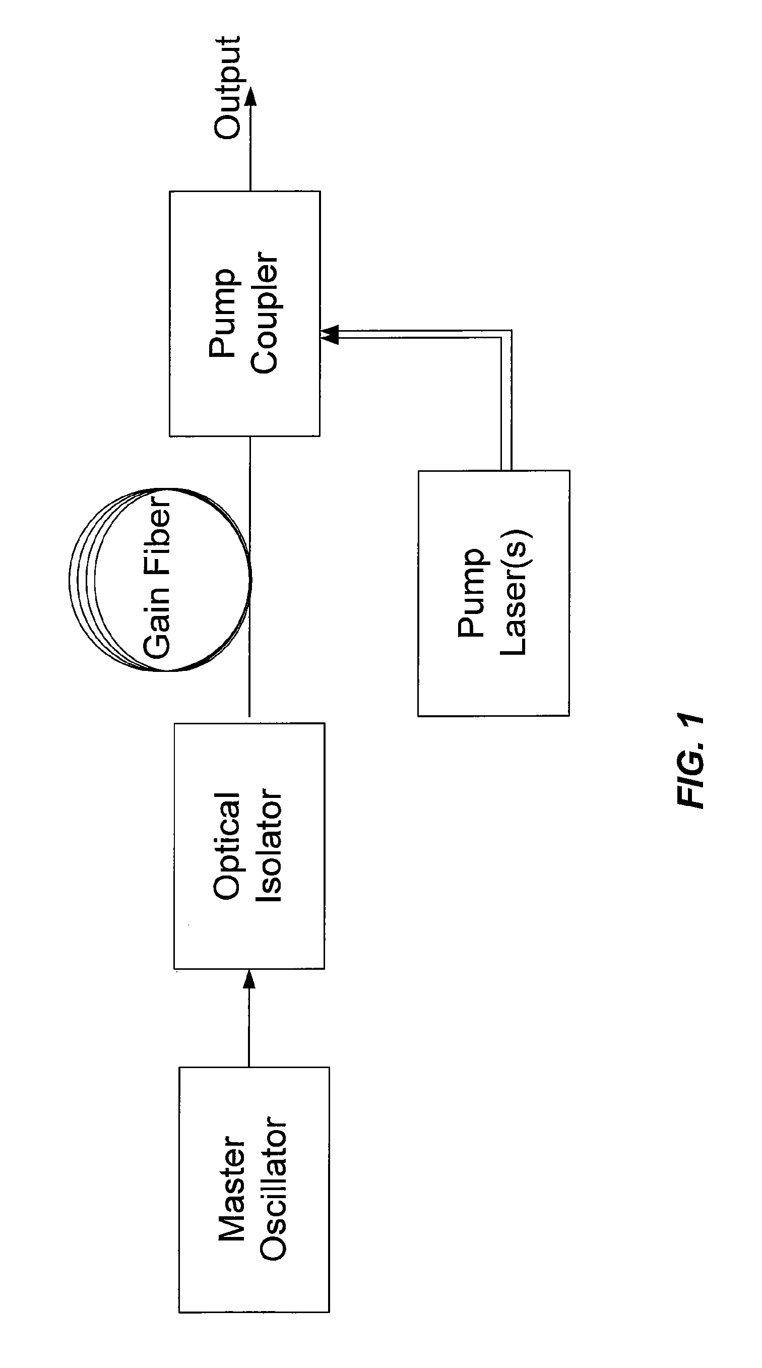
CROSS-REFERENCES TO RELATED APPLICATIONS[0001]The present application claims benefit under 35 U.S.C. §119(e) of U.S. Provisional Patent Application No. 60 / 976,202, filed on Sep. 28, 2007, entitled “Fast Pulse Harmonic Fiber Laser” the disclosure of which is hereby incorporated by reference in its entirety for all purposes.BACKGROUND OF THE INVENTION[0002]This invention relates generally to high performance pulsed laser frequency conversion systems that operate with high power, visible and near-infrared spectral output, narrow spectral linewidths, and freedom to adjust pulse parameters and characteristics.[0003]Fiber lasers have advanced to become economical and efficient high power infrared laser sources. Average optical output powers of tens of kilowatts are currently available in commercial fiber laser systems. FIG. 1 is a schematic of a typical fiber laser system known in the art with a master oscillator fiber amplifier (MOFA) architecture. The master oscillator (also known as th...

Claims


Application Information

Patent Timeline
Patent Type & Authority Patents(United States)
IPC IPC(8): H01S3/30
CPCH01S3/2316G02F1/3551H01S5/146H01S3/0057H01S3/0064H01S3/0092H01S3/06712H01S3/06754H01S3/094007H01S3/09408H01S3/09415H01S3/1118H01S3/1618H01S5/0657G02F1/37
Inventor MUNROE, MICHAEL J.ALEKEL, THEODOREDUTTON, DAVID A.FOSTER, DAVID H.LACHAPELLE, JOSEPH G.
Owner DEEP PHOTONICS CORP
Learn More