
Reusable holder for transmission electron microscope, scanning electron microscope, and focused ion beam samples

a technology of scanning electron microscope and ion beam sample, which is applied in the field of reusable holder for transmission electron microscope, scanning electron microscope, and focused ion beam sample, can solve the problems of inherently destructive fib, limited magnification achievable with light microscope, and high cost of sample preparation using fib, so as to facilitate proper loading and facilitate confirmation

Active Publication Date: 2010-07-20
TED PELLA
View PDF19 Cites 12 Cited by
  • Summary
  • Abstract
  • Description
  • Claims
  • Application Information

AI Technical Summary

Benefits of technology

[0017]In a broad aspect of the invention, an assembly is provided which generally comprises a first part having a first holding portion and a second part in engagement with the first part and having a second holding portion substantially facing the first holding portion, and a resilient member positioned to provide a compressive force between the first part and the second part. The compressive force is sufficient to secure a material sample located between the first holding portion and the second holding portion, preferably without causing damage to the sample. The assembly further comprises a mounting element operable to secure the first part and the second part to an instrument or device, for example a microscopy instrument, such as a FIB, or a sample storage / transport container. The assembly may further comprise one or more alignment elements for ensuring proper alignment of the parts.
[0026]In another broad aspect of the invention, an assembly for holding microscopy samples comprises a sample holder including a first part and a second part cooperatively engaged with the first part, a mechanism for providing compression between the first part and the second part in order to secure a material sample positioned therebetween, a mounting element operable to secure the sample holder to a microscopy instrument, and a base member removably couplable to the mounting element. The base member provides a convenient means for holding the sample holder when the sample holder and sample secured thereto are being stored or otherwise not coupled to a microscopy instrument. In some embodiments, the base member is advantageously structured so as to maintain a eucentric position of a sample held in the assembly. With this embodiment, it is possible to observe a sample, for example, by using a stereoscope, at two different angular positions, without the need to refocus the stereoscope. This embodiment of the invention is especially advantageous to facilitate proper loading of a sample, as well as to facilitate confirmation that the sample is correctly placed in the holder prior to further, more detailed observation or processing with a TEM and / or FIB.

Problems solved by technology

With a good light microscope (also referred to as an “optical microscope”), an image may be magnified up to about 1500 times. However, magnification achievable with light microscopes is limited by the physics of light (i.e., the wavelength of light) upon which the operation of such microscopes is based.
Unlike SEM, the FIB is inherently destructive to the sample.
The preparation of samples using an FIB involves considerable cost because of the time of preparation and the high capital expense of the processing instruments.
Further, TEM grid mounted samples are prone to breakage and damage due to the delicate structures of the materials mounted on the grid, as well as the fragile structure of the grid itself.
Holders, for example, TEM grid boxes, have been developed for holding TEM grid-mounted samples, but none have proven to be adequate in protecting the samples from breakage, damage or loss, for example, during handling or during transportation.
Even very minor flexing of the grid can endanger the sample mounted thereto.
However, these membrane boxes have been known to cause damage to samples.

Method used


Image

  • Reusable holder for transmission electron microscope, scanning electron microscope, and focused ion beam samples
  • Reusable holder for transmission electron microscope, scanning electron microscope, and focused ion beam samples
  • Reusable holder for transmission electron microscope, scanning electron microscope, and focused ion beam samples

Examples


Embodiment Construction

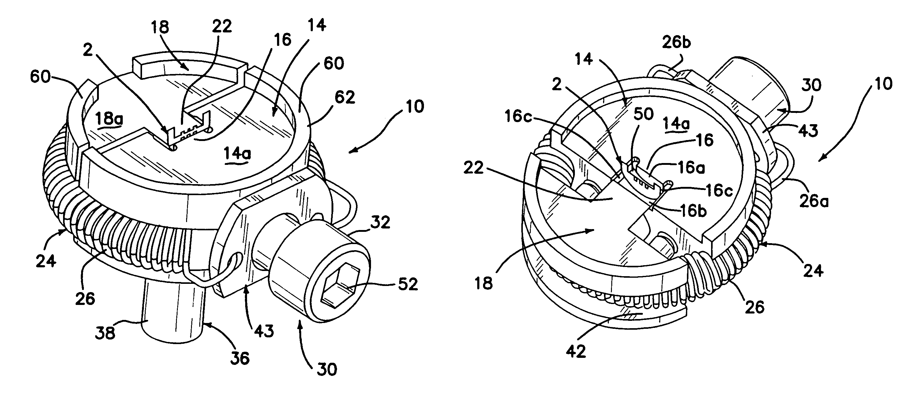
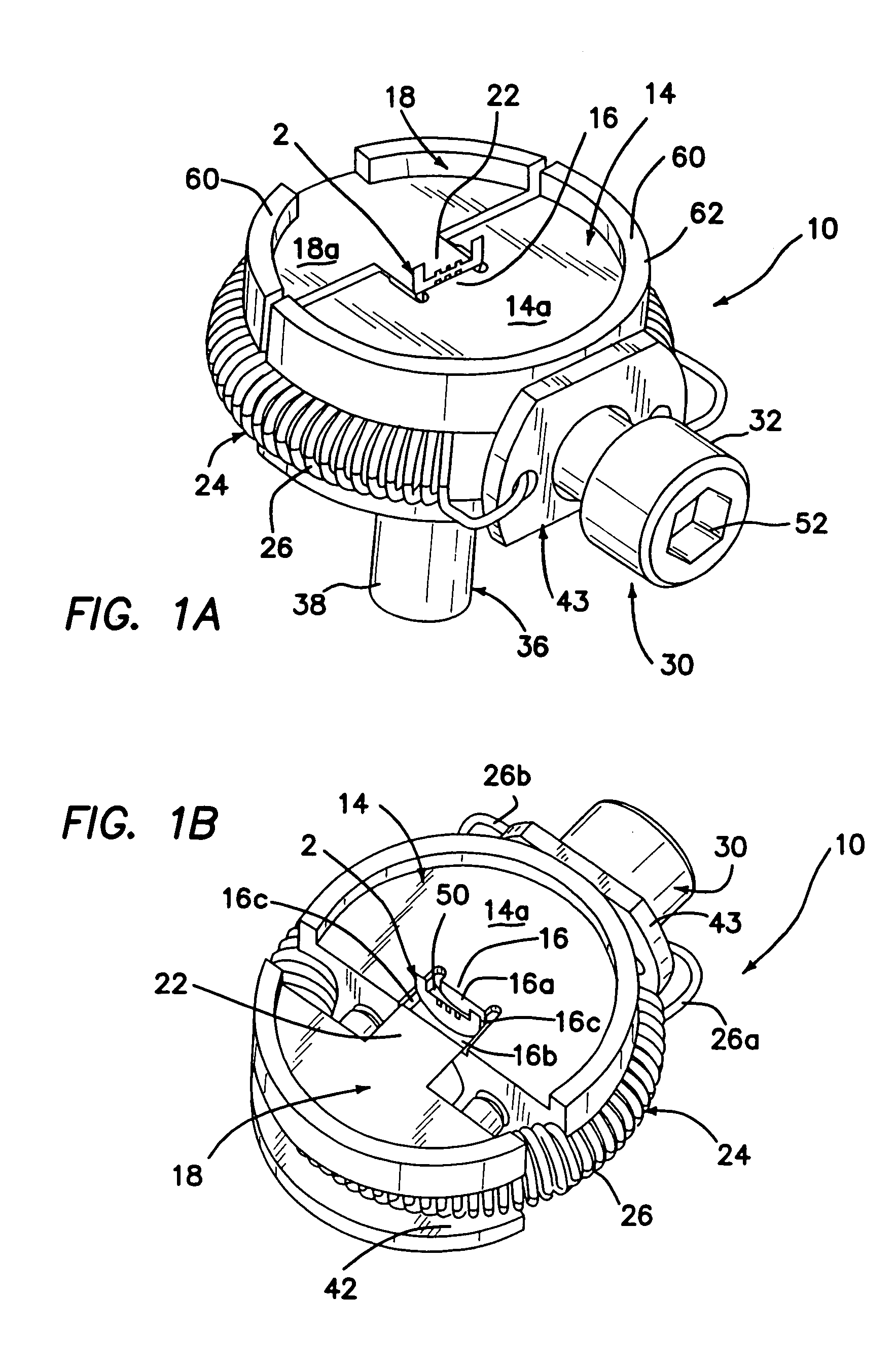
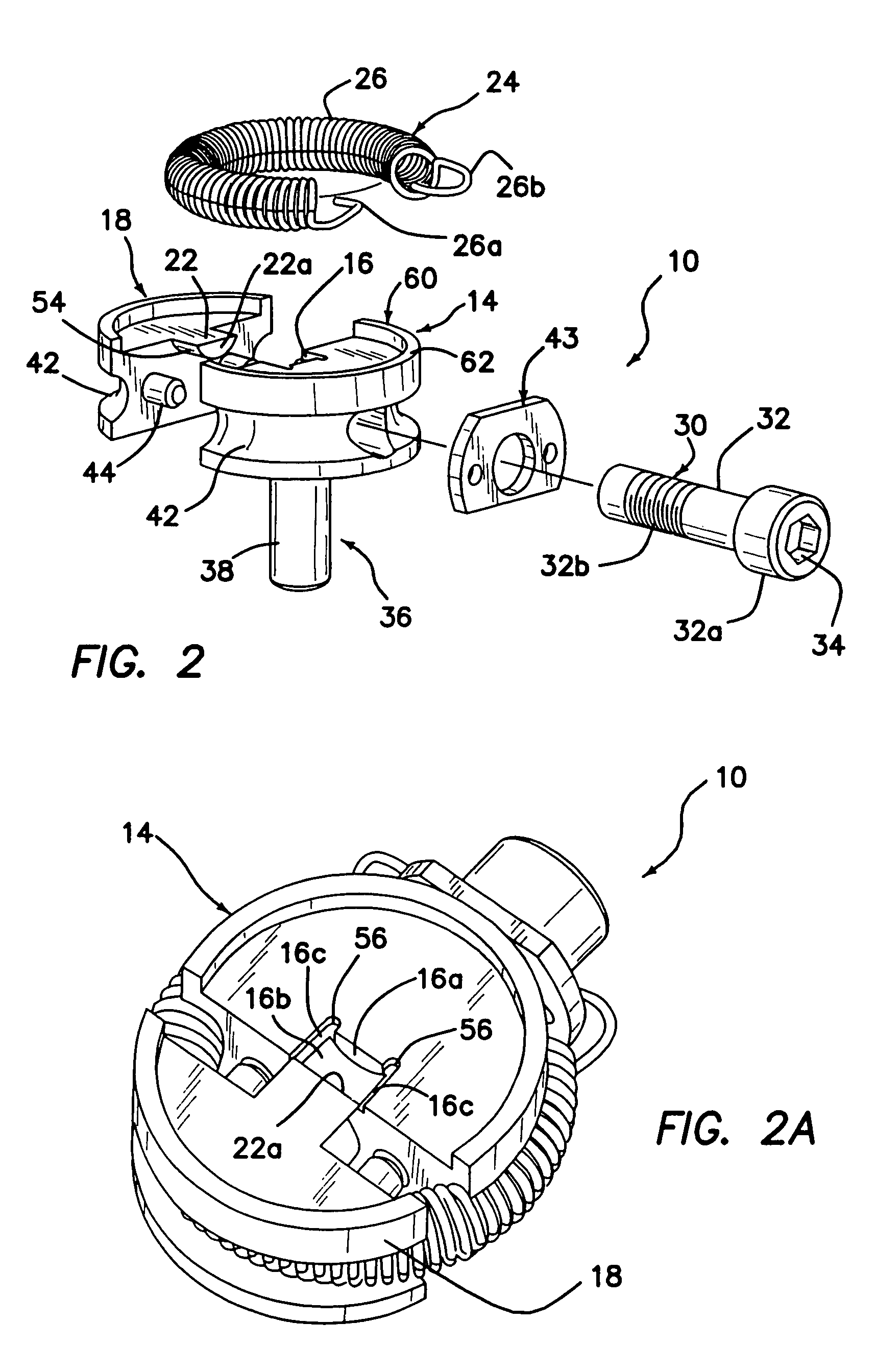
[0038]Turning to FIGS. 1A, 1B and 2, an assembly, in accordance with the invention, for holding transmission electron microscope (TEM), scanning electron microscope (SEM), and focused ion beam (FIB) samples is generally shown at 10.

[0039]The assembly 10 can be used to hold a sample, specifically a microscopy sample 2, for storage, observation, manipulation, characterization and / or study of the sample, for example, when the assembly 10 is positioned in a microscopy instrument. The assembly 10 is capable of safely securing such samples in a desired orientation preferably without the use of adhesives, adhesive pads, or conductive paint. Advantageously, in the embodiment shown, the assembly 10 is structured to be useful for securing two or more different types of microscopy samples, including, but not limited to, whole or cut samples, fiber samples, TEM grid-mounted samples and diced samples.

[0040]The assembly 10 may generally comprise a first part 14 having a first holding portion 16, ...


PUM


Abstract

An assembly for holding a microscopy sample for storage, observation, manipulation, characterization and / or study of the sample using a microscopy instrument is provided. The assembly includes mating first and second parts having faces between which a microscopy sample, including a TEM grid mounted sample, is secured. A spring is used to provide compression between the faces. A rotatable member such as a threaded screw is operable to draw the parts apart from one another. An annular wall functions to protect microscopy samples held in the assembly from damage.

Description

[0001]The present application claims priority to U.S. Provisional Patent Application No. 60 / 778,237, filed on Mar. 1, 2006, the entire disclosure of which is incorporated herein by this reference.[0002]The present invention generally relates to assemblies for holding material specimens, and more specifically relates to assemblies for holding, but not limited to, transmission electron microscope (TEM), scanning electron microscope (SEM), and focused ion beam (FIB) atomic force microscope (AFM), field ion microscope (FIM), atom probe (AP) samples, and other types of for observation, processing and / or storage.BACKGROUND[0003]Much development is being achieved on the micrometer (μm) and nanometer (nm) size scales in the fields of biology, medicine, physics, chemistry, electronics, engineering, and nanotechnology to, for example, study objects (e.g., materials, organisms, viruses, bacteria, etc.), create new objects, and / or assemble objects together with great precision.[0004]To perform ...

Claims


Application Information

Patent Timeline
Patent Type & Authority Patents(United States)
IPC IPC(8): G21K5/08H01J37/20
CPCH01J37/20H01J2237/2007
Inventor WALCK, SCOTT D.HENRIKS, DAVID J.
Owner TED PELLA
Learn More