Supercharge Your Innovation With Domain-Expert AI Agents!

Charged particle beam writing method

a technology of charged particles and writing methods, applied in the field of pattern writing methods with charged particle beams, can solve the problems of difficult to cope with such three error factors, deterioration of pattern dimension accuracy, etc., and achieve the effect of removing detrimental effects

Active Publication Date: 2010-07-20
NUFLARE TECH INC
View PDF3 Cites 4 Cited by
  • Summary
  • Abstract
  • Description
  • Claims
  • Application Information

AI Technical Summary

Benefits of technology

The present invention provides methods for improving the resolution of a beam of charged particles in a mask writing system. These methods involve emitting two charged particle beams that are shaped by two separate apertures in a mask. The first beam is shaped by passing through both a first and second aperture, while the second beam is shaped by passing through the same apertures as the first beam but with opposite sides. By positioning the second beam in a way that its shape is adjacent to the first beam, but with corresponding sides that face each other, the detrimental effects of beam resolution degradation caused by the space charge effect can be eliminated. This results in improved accuracy and precision in the writing process.

Problems solved by technology

Thus, variations of development time cause deterioration of pattern dimension accuracy.
It is not easy to cope with such three error factors.

Method used


Image

  • Charged particle beam writing method
  • Charged particle beam writing method
  • Charged particle beam writing method

Examples


embodiment 1

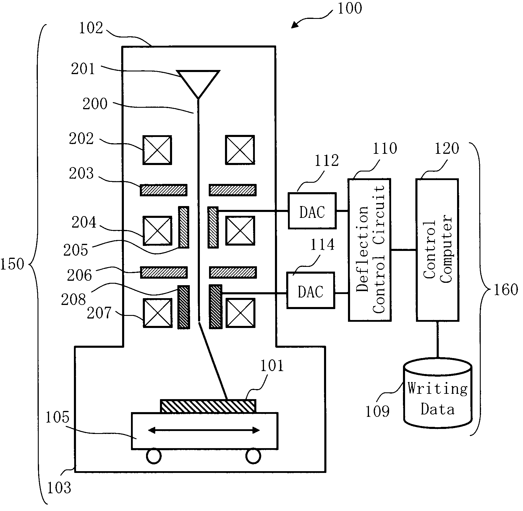
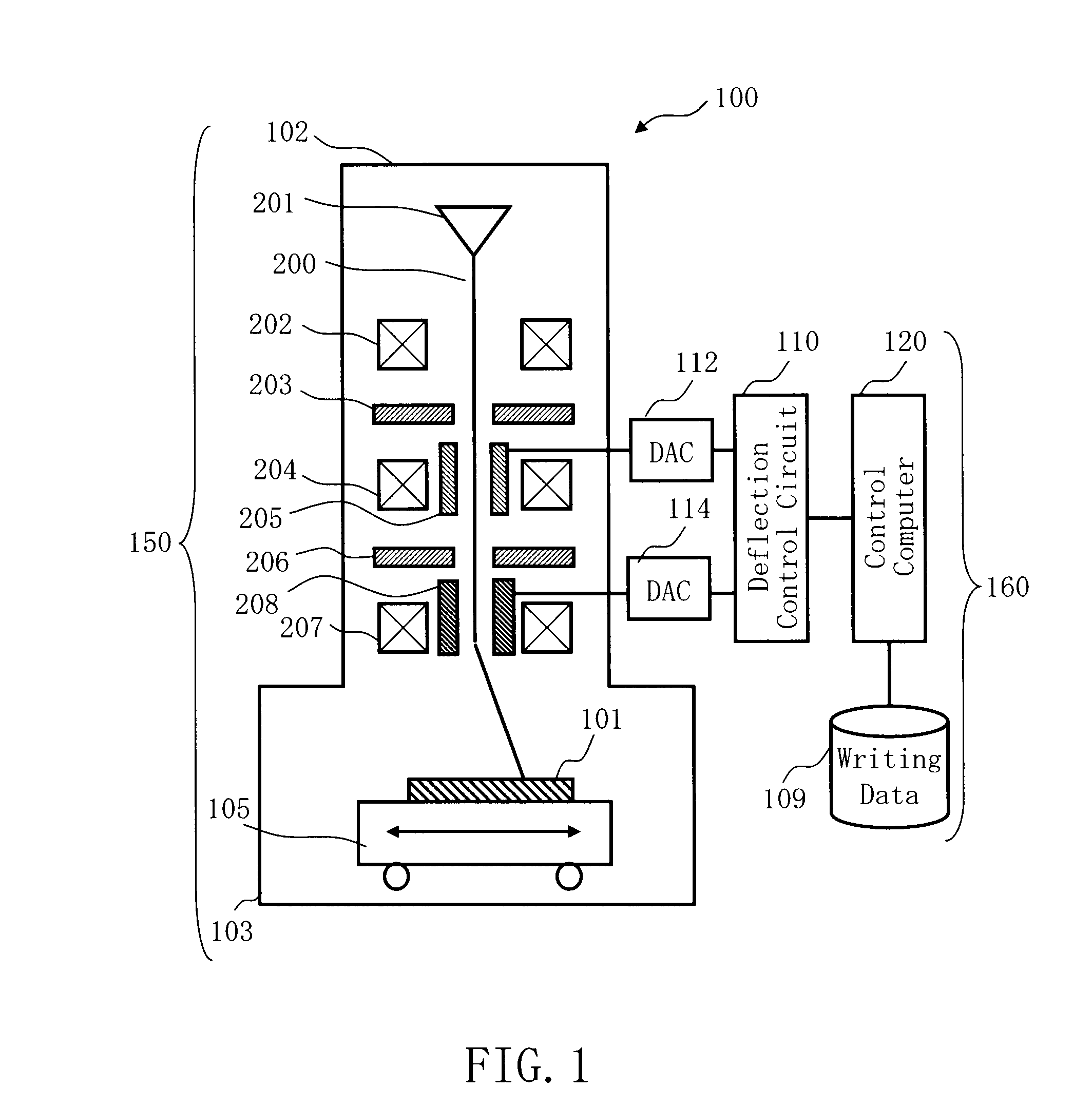
[0034]FIG. 1 shows a schematic diagram illustrating a structure of a writing apparatus described in Embodiment 1. In FIG. 1, a pattern writing apparatus 100 includes a writing unit 150 and a control unit 160. The pattern writing apparatus 100 serves as an example of a charged particle beam writing apparatus. The pattern writing apparatus 100 writes a desired pattern on a target workpiece 101. The control unit 160 includes a control computer 120, a deflection control circuit 110, a magnetic disk drive 109, and digital-to-analog converters (DAC) 112 and 114. The writing unit 150 includes an electron lens barrel 102 and a writing chamber 103. In the electron lens barrel 102, there are an electron gun assembly 201, an illumination lens 202, a first shaping aperture 203, a projection lens 204, a shaping deflector 205, a second shaping aperture 206, an objective lens 207, and a deflector 208 adequately arranged. In the writing chamber 103, there is an movable XY stage 105 adequately arran...

embodiment 2

[0051]In Embodiment 1, the case of eliminating detrimental effects caused by beam resolution degradation by performing multiplex writing has been explained. However, even if the multiplex writing is not performed, there is a case of eliminating the detrimental effects by another way of writing. In Embodiment 2, a writing method which suppresses beam resolution degradation, without performing multiple writing will be described. The apparatus structure in Embodiment 2 is the same as that of FIG. 1.

[0052]It is described in Embodiment 2 how to form one pattern with two or more shots.

[0053]FIGS. 9A to 9E show examples of forming a beam for writing one pattern with two shots, beam profiles of two shots to be combined, and a beam profile after combining. In the present Embodiment, as explained below, the electron beam 200 (first charged particle beam) is formed so that the side located opposite to the combining direction may become the side formed by the second shaping aperture 206. First,...


PUM


Abstract

A writing method includes emitting a first charged particle beam formed to be a first shape by passing through a first shaping aperture and a second shaping aperture, onto a target workpiece; and emitting a second charged particle beam formed to be a second shape by passing through the first shaping aperture and the second shaping aperture, wherein the second charged particle beam is superimposed onto a same position exposed by the first charged particle beam and is formed by using an opposite sides of respective first and second shaping apertures to those used for the first shape.

Description

CROSS-REFERENCE TO RELATED APPLICATION[0001]This application is based upon and claims the benefit of priority from the prior Japanese Patent Application No. 2007-222646 filed on Aug. 29, 2007 in Japan, the entire contents of which are incorporated herein by reference.BACKGROUND OF THE INVENTION[0002]1. Field of the Invention[0003]This invention relates to a pattern writing method with charged particle beam, and for example, to a writing method of a writing apparatus which varies a beam shape by letting the beam pass through two shaping apertures.[0004]2. Description of Related Art[0005]The lithography technique that drives advancement of micro-scaling of semiconductor devices is extremely important being the only process to form patterns in semiconductor manufacturing processes. In recent years, with high integration of large-scale integrated circuits (LSI), critical dimensions required for semiconductor device circuits are shrinking year by year. In order to form a desired circuit ...

Claims


Application Information

Patent Timeline
Patent Type & Authority Patents(United States)
IPC IPC(8): G21K1/00G21K5/10
CPCB82Y10/00B82Y40/00G03F7/2059H01J37/3026H01J37/3174H01J2237/30472
Inventor ABE, TAKAYUKIYAMAGUCHI, TETSUOHIDE, FUMIO
Owner NUFLARE TECH INC
Features
  • R&D
  • Intellectual Property
  • Life Sciences
  • Materials
  • Tech Scout
  • Unparalleled Data Quality
  • Higher Quality Content
  • 60% Fewer Hallucinations
Learn More