Intervention rod

a technology of intervention rods and rods, which is applied in the direction of drilling pipes, wellbore/well accessories, sealing/packing, etc., can solve the problems of buckling, more difficult and costly to add sensing fibres, and more difficult and expensive to deploy sensing fibres

Active Publication Date: 2010-08-03
ZIEBEL AS
View PDF11 Cites 46 Cited by
  • Summary
  • Abstract
  • Description
  • Claims
  • Application Information

AI Technical Summary

Benefits of technology

[0015]The use of a barrier layer can provide a number of advantages compared to known resin coated fibres for example. Firstly the service line can be protected somewhat from stresses in the stiff structure when the rod is pushed into the conduit. Such stresses can include axial compression and radial compression from impeller wheels. This is particularly important for service lines such as optical fibres. Secondly, the service line can be protected from stresses or high temperatures when the stiff structure is formed. This can enable stiffer or lighter materials to be used for the stiff structure for example. Thirdly the barrier can help enable the rod to have a broader cross section for more stiffness for a given weight.
[0036]The use of pressure to control movement of the piston can enable a more compact arrangement than known arrangements relying on gravity. It can also enable safer operation since the relative pressure across the piston can be monitored more easily.

Problems solved by technology

A typical wellbore has seepage of unwanted contaminants, especially in later stages of the production life of an oil or gas field.
Once the pipe or bore is in use, and carrying a fluid, typically pressurised, it is more difficult and costly to add a sensing fibre, or to deploy one temporarily and withdraw it after sensing.
A problem with coiled tubing is that it is subjected to buckling due to the nature of the coil being bent on a spool when deployed, even though straightening mechanism are used on the coil before this enters the wellbore.
This is not far enough into the wellbore for many applications.
Both these methods (“tractor” and coiled tubing) are expensive in terms of requiring a considerable number of personnel to operate, and in the case of coiled tubing, the surface systems are large and it can take a long time to rig up on the wellhead.
In some locations, especially on offshore platforms, such vertical rig-up space is not available due to a deck or similar structure above.
The strengthened fibre is flexible enough to be bent round a 12 inch radius, and so could be liable to buckle if inserted into a large diameter pipe.
This capillary tube would be pre installed within the wellbore, but this involves a separate process which adds considerable cost and complexity.
This clearly is not practical if the normal flow is against the direction of insertion.
In some cases a separate narrower duct could be inserted into the conduit and the fibre floated into the duct, but this adds to the complexity and expense of the operation.

Method used


Image

  • Intervention rod
  • Intervention rod
  • Intervention rod

Examples


Embodiment Construction

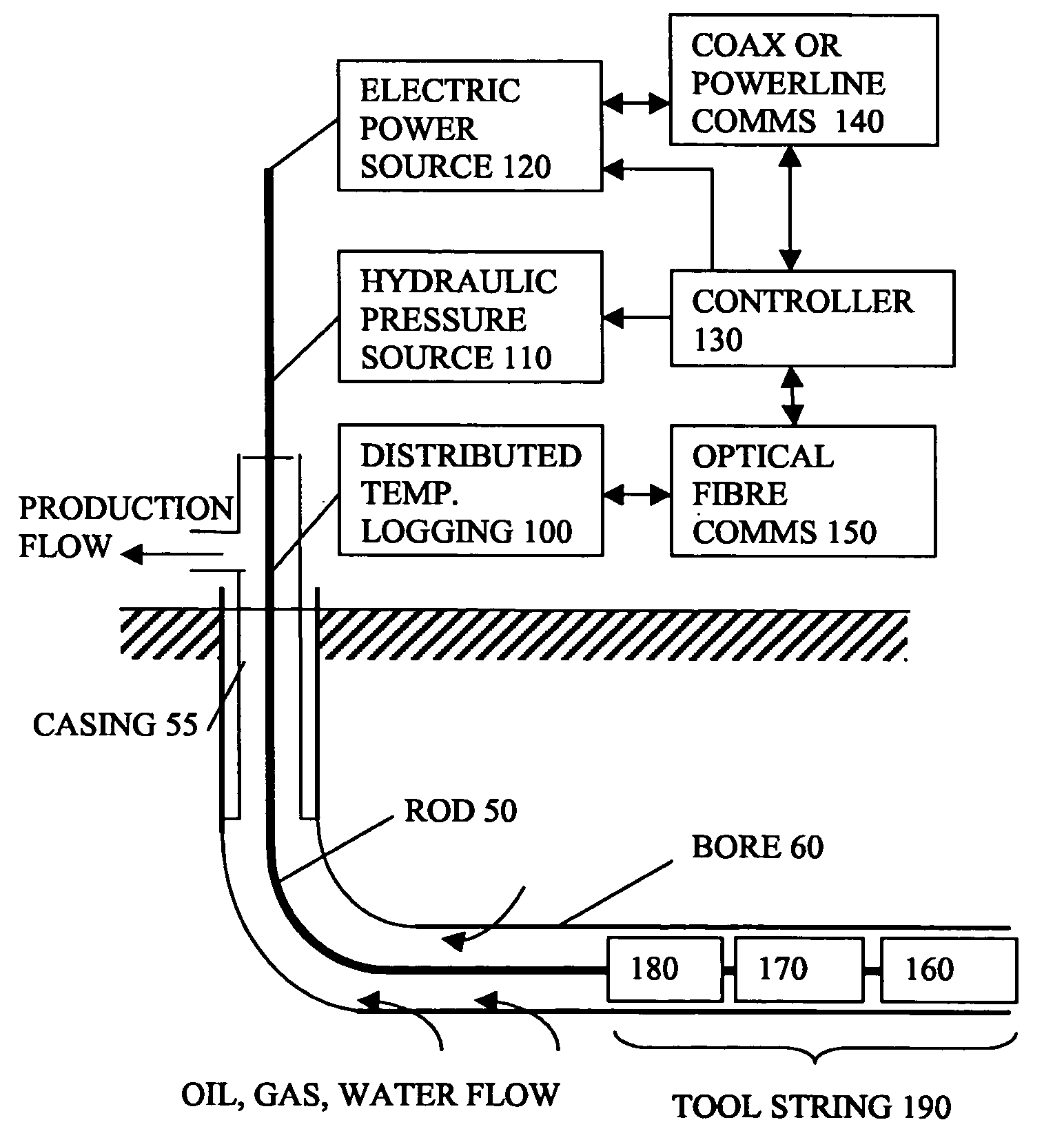
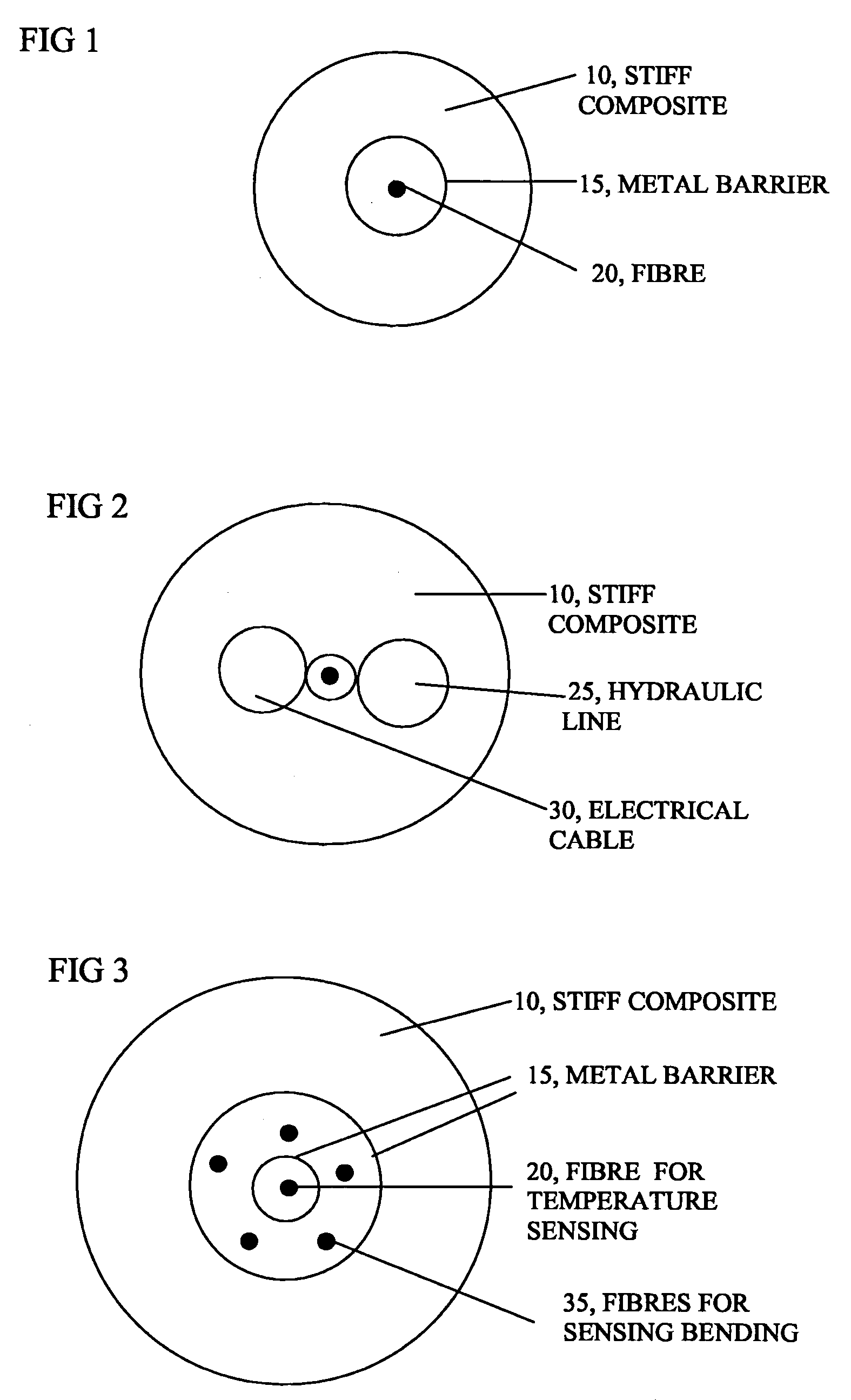
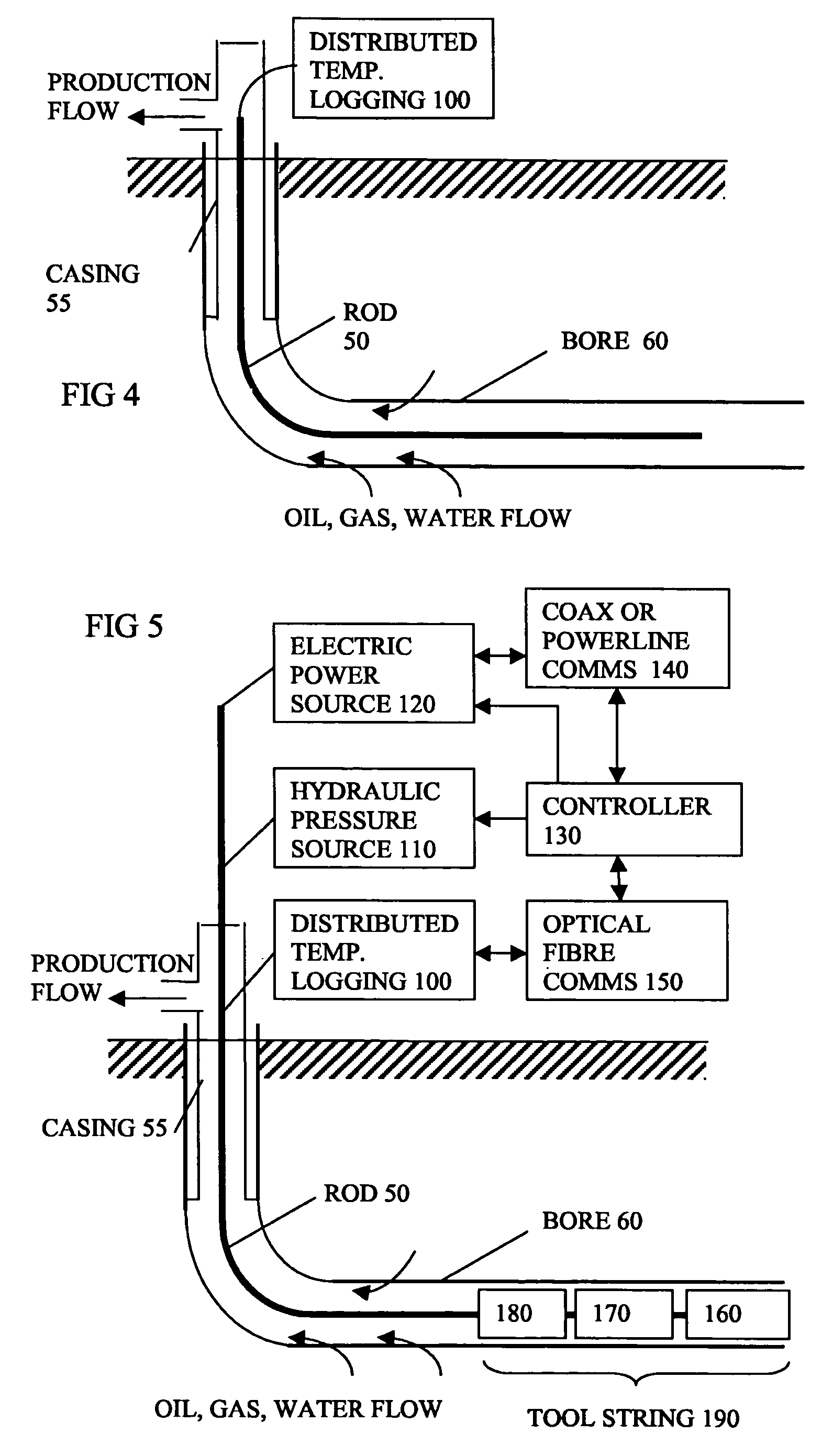
[0048]The embodiments described relate to performing a distributed temperature logging or other actions in a conduit such as a wellbore by inserting / pushing a stiff spooled intervention rod, for example manufactured of a composite or a hard plastic material, into the wellbore from one end. Clearly the aspects of the invention can be applied or implemented in other ways. In cases where the wellbore contains elevated pressure, a sealing system against the intervention rod must be used to prevent wellbore fluid leakages to the environment. As the intervention rod is manufactured to be straight and stiff, the rod can be pushed into the conduit without risk of buckling and jamming in the conduit, or for longer distances before friction between the rod and the conduit becomes too great.

[0049]The intervention rod can be pushed from surface, using an injector system constructed with feeding wheels, chain drive, or similar, and it can be pushed to a desired distance. This distance can be as ...


PUM

PropertyMeasurementUnit
diameteraaaaaaaaaa
diameteraaaaaaaaaa
angleaaaaaaaaaa

Abstract

A rod having an embedded optical fiber has a stiff composite outer layer (10) to make the rod self straightening to enable it to be pushed into a pipe or borehole from a spool. This can help enable a reduction of friction between rod and conduit and can enable longer reach. A barrier layer is provided to separate the fiber from the composite layer. The rod can be retrieved after use. The rod can be narrow enough to enable normal flow along the pipe or borehole, and can be injected and retrieved even when the pipe or borehole is pressurized. The fiber can be used for remote sensing of conditions along the conduit. Other tools can be inserted by the rod during the intervention.

Description

FIELD OF THE INVENTION[0001]The present invention relates to rods for intervention in conduits such as wellbores, to methods of manufacturing the same, to systems for monitoring such conduits, to apparatus for injecting a rod into a conduit, and apparatus for removing plugs to allow insertion of rods into pressurised conduits, to methods of carrying out an intervention process and to methods of operating a fluid transmission conduit.BACKGROUND[0002]There is a requirement in industry for the measurement of conditions such as strain or temperature at all points over long distances. Typical uses are for monitoring oil and gas wells, long cables and pipelines. A typical wellbore has seepage of unwanted contaminants, especially in later stages of the production life of an oil or gas field. Temperature profiles along the wellbore can indicate where there are seepages or other problems and this can enable remedial action. Distributed temperature sensors often use Raman or Brillouin compone...

Claims


Application Information

Patent Timeline
Patent Type & Authority Patents(United States)
IPC IPC(8): G02B6/44F16K51/00H02G1/08B23P11/00E21B19/22E21B43/00E21B23/14E21B33/072E21B47/00E21B17/20E21B23/08
CPCE21B17/206G02B6/4464E21B23/08Y10T29/49826Y10T137/598G02B6/52
Inventor HANSEN, HENNINGFARHADIROUSHAN, MAHMOUDKLUTH, RICHARD JULIUS
Owner ZIEBEL AS
Why Eureka
Try Eureka