Current converter, frequency mixer, radiofrequency transmission system and method for frequency mixing

a technology of frequency mixer and current converter, which is applied in the direction of electric/magnetic computing, computation using denominational number representation, instruments, etc., can solve the problems of increasing widening the modulation spectrum, and disturbing the adjacent frequency channels, etc., and achieving the effect of reducing the space requirement on the chip

Inactive Publication Date: 2010-08-10
INTEL CORP
View PDF6 Cites 7 Cited by
  • Summary
  • Abstract
  • Description
  • Claims
  • Application Information

AI Technical Summary

Benefits of technology

[0018]In one embodiment, current conversion is effected by actuating the first and second transistors with the output signals from the second differential amplifier. Resistance-based or impedance-based feedback of signals on the first and second transistors to the inputs of the second differential amplifier linearizes the current conversion, that is to say that a differential output current at the differential current output of the current converter is linearly dependent on a differential input signal at the differential signal input. Harmonics in the differential output current are therefore reduced.
[0021]The use of a current converter with reduced harmonics in the differential output current in one embodiment of the frequency mixer allows frequency mixing to be achieved in which intermodulation products in the mixed radiofrequency output signal are reduced in comparison with a conventional frequency mixer.
[0022]In another embodiment of the frequency mixer, a second or further mixer cell may be provided which has its current input connected to the differential current output of the current converter. By way of example, the further mixer cell is designed for a different frequency band than the first mixer cell. In this case, the mixer cells are supplied with oscillator signals at different oscillator frequencies. The use of a common current converter for a plurality of mixer cells allows the space requirement on the chip to be reduced when integrating the frequency mixer in an integrated circuit.
[0024]In one embodiment, producing the feedback signal in the first amplification device and supplying the feedback signal to the second amplification device allows linearization of a differential current in the first amplification device with respect to the differential input signal. This in turn results in reduced intermodulation products in the differential output signal from the mixer cell.

Problems solved by technology

Particularly the third harmonic can widen the modulation spectrum and disturb the adjacent frequency channels.
Hence, the signal quality of the mixed signal can be impaired, which is manifested by an increased bit error rate or an impaired error vector magnitude (EVM), for example.
However, the resistive negative feedback increases the thermal noise in the frequency mixer, while the gain falls.
A larger operating current in the frequency mixer usually increases shot noise in a bipolar transistor or channel noise in a field effect transistor on account of the necessary increase in the size of the transistor channel.
Lowering the input amplitude in turn regularly results in impairment of the efficiency of the frequency mixer.
This is problematical particularly because the thermal noise in the frequency mixer can dominate the overall noise in a transmitter.

Method used


Image

  • Current converter, frequency mixer, radiofrequency transmission system and method for frequency mixing
  • Current converter, frequency mixer, radiofrequency transmission system and method for frequency mixing
  • Current converter, frequency mixer, radiofrequency transmission system and method for frequency mixing

Examples


Embodiment Construction

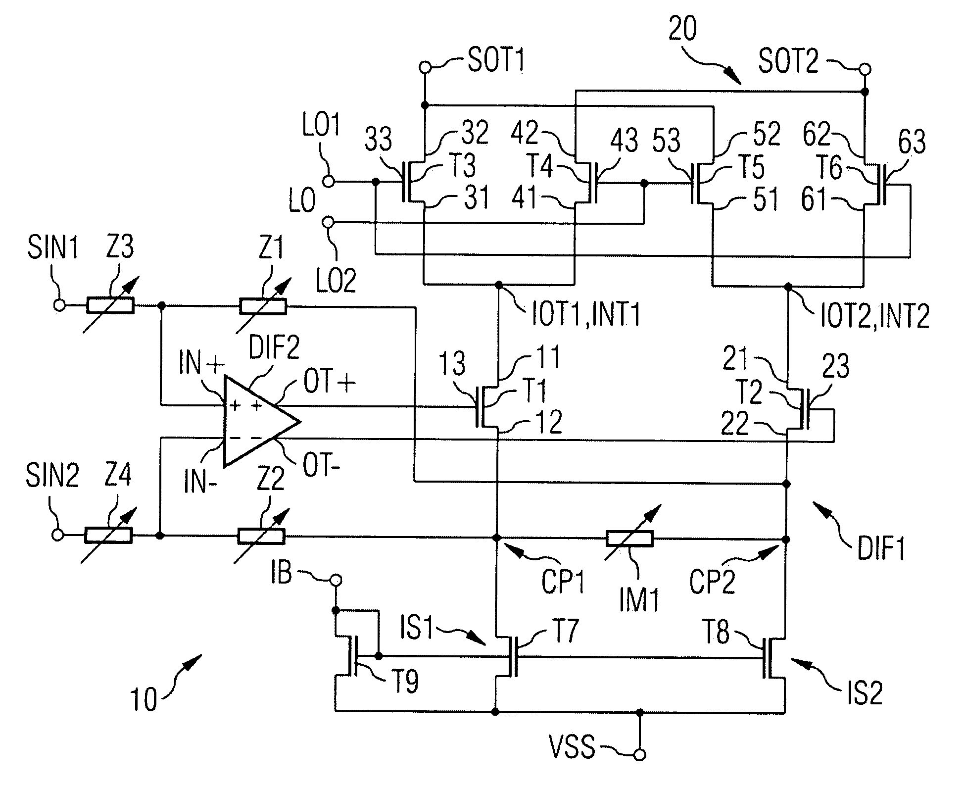
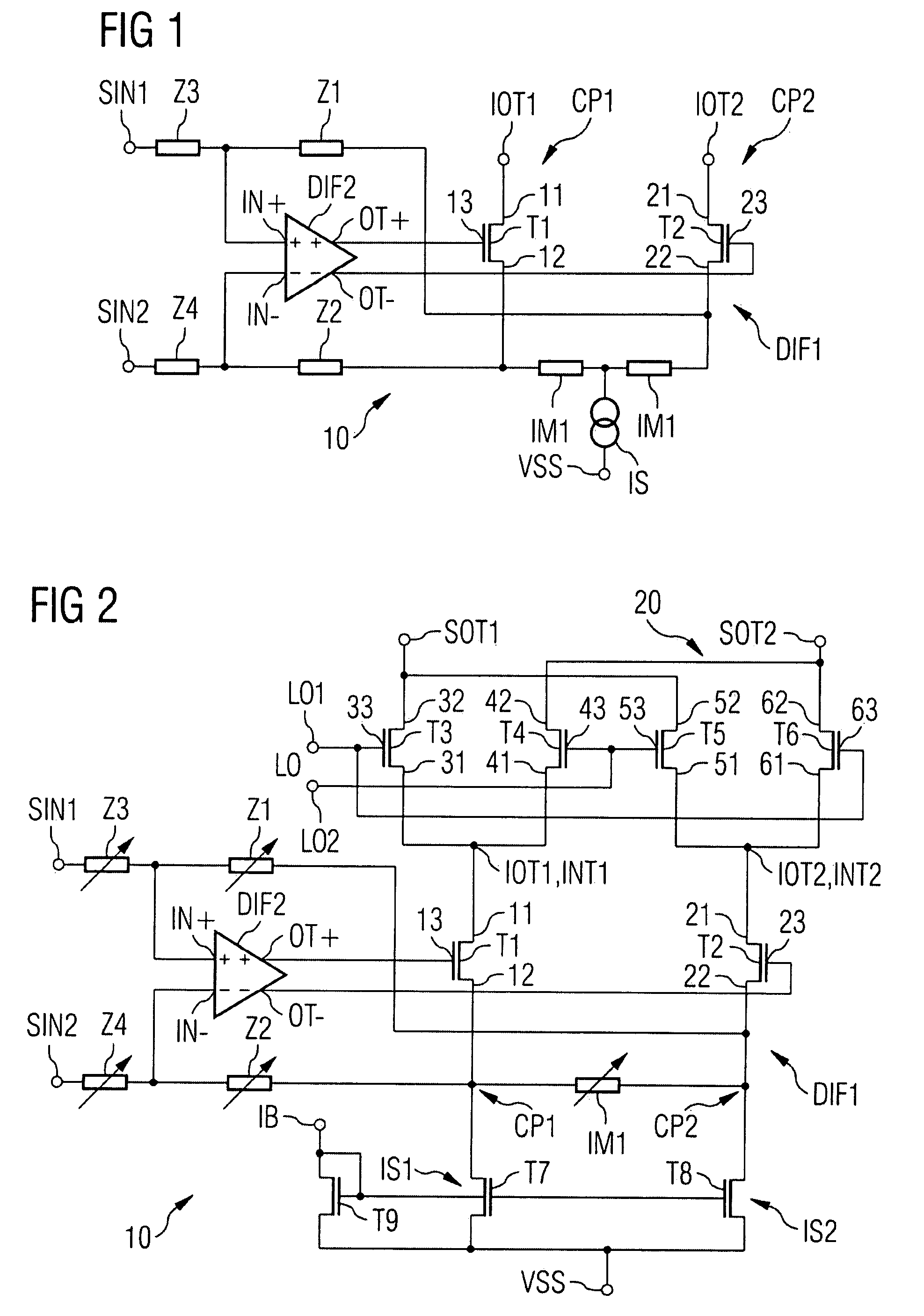
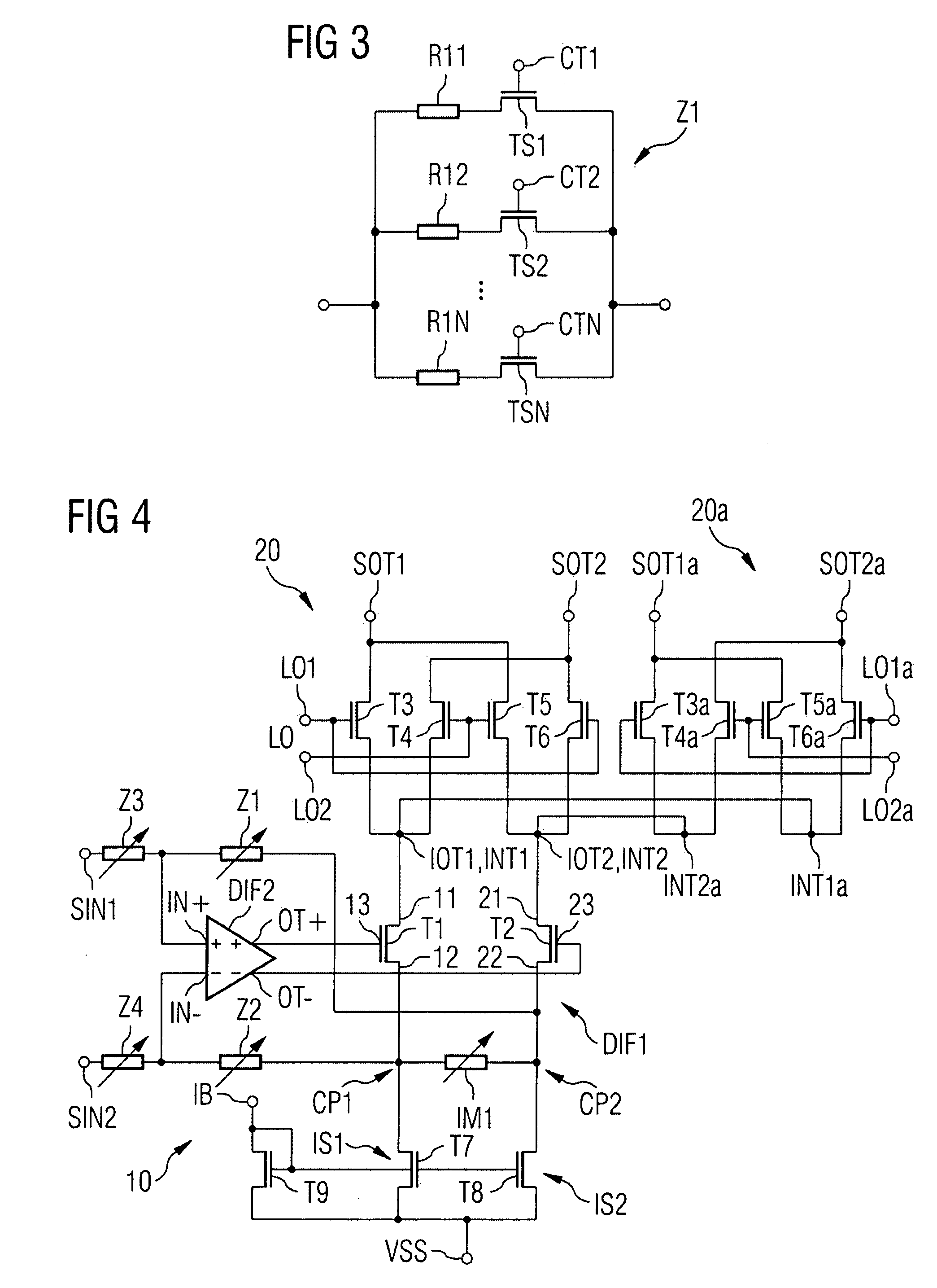
[0035]In the following description further aspects and embodiments of the present invention are disclosed. In addition, reference is made to the accompanying drawings, which form a part hereof, and in which is shown by way of illustration, in which the invention may be practiced. The embodiments of the drawings present a disclosure in order to provide a better understanding of one or more aspects of the present invention. This disclosure is not intended to limit the features or key-elements of the invention to a specific embodiment. Rather, the different elements, aspects and features disclosed in the embodiments can be combined in different ways by a person skilled in the art to achieve one or more advantages of the present invention. It is to be understood that other embodiments may be utilized and structural or logical changes may be made without departing from the scope of the present invention. The elements of the drawing are not necessarily to scale relative to each other. Lik...


PUM


Abstract

A current converter has a first amplification device, which outputs a differential current depending on a differential control signal and derives a differential feedback signal from the differential current. The current converter also has a second amplification device, which amplifies a differential input signal at its input depending on the differential feedback signal to form the differential control signal. The current converter may be used in a frequency mixer together with a mixer cell which produces a differential output signal by multiplying the differential current and an oscillator signal.

Description

REFERENCE TO RELATED APPLICATIONS[0001]This application claims the benefit of the priority date of German application DE 10 2006 043 902.3, filed on Sep. 19, 2006, the contents of which are herein incorporated by reference in their entirety.FIELD OF THE INVENTION[0002]The invention relates to a current converter. The invention also relates to a frequency mixer having a current converter and to a radiofrequency transmission system. The invention furthermore relates to a method for frequency mixing.BACKGROUND OF THE INVENTION[0003]The demands on modern communication standards and on the signal quality of transmission devices are rising with the growing need for high data rates and increasing mobility. Mobile radio standards which have now become customary, such as Universal Mobile Telecommunications System (UMTS), Wideband Code Division Multiple Access (WCDMA), Global System for Mobile Communications (GSM), Enhanced Data Rates for GSM Evolution (EDGE), Wireless Local Area Network (WLA...

Claims


Application Information

Patent Timeline
Patent Type & Authority Patents(United States)
IPC IPC(8): H04B1/26
CPCH03F1/3211H03F1/342H03F3/245H03F3/45179H03F3/45475H03F2200/451H03F2203/45522H03F2203/45591H03F2203/45652
Inventor SIMON, MARTIN
Owner INTEL CORP
Why Eureka
Try Eureka