Solvent filtration system and methods

a solvent and filter system technology, applied in the direction of filtration separation, sedimentation settling tanks, separation processes, etc., can solve the problems of contaminating the environment, endanger operating personnel, and undetected acceleration of pipe erosion, so as to minimize solvent loss and eliminate displacement vapors from the environment

Inactive Publication Date: 2010-08-31
FLUOR TECH CORP
View PDF1 Cites 4 Cited by
  • Summary
  • Abstract
  • Description
  • Claims
  • Application Information

AI Technical Summary

Benefits of technology

[0008]The present invention provides improved solvent based filtration systems in which loss of solvent and venting of displacement vapors into the environment are minimized, or even entirely eliminated. Implementations of the invention are contemplated to be particularly useful in larger refining facilities and in gasification plants, and even smaller facilities that utilize expensive solvents.

Problems solved by technology

Unless removed, these and other solids tend to foul columns, vessels, heat exchangers, and carbon bed filters.
They can also erode the protective iron sulfide films from internal piping surfaces, thereby undesirably accelerating pipe erosion.
Improper handling of such contaminates can potentially endanger operating personnel and contaminate the environment.
But the use of disposable media entails repeated media purchases and potentially costly installation.
Moreover, replacement of filter cartridges and other disposable media often requires special procedures due to the presence of hazardous gases in the filtered materials.
In addition, disposable media are themselves waste products, and pose their own waste disposal issues.
Although contemporary clean-in-place filters are capable of removing solids and particles from a solvent, and although the cleaning process can be automated to some extent to avoid the hazards and costs associated with the manual replacement of filter elements, the contemporary backwashing process in such systems also tends to undesirably remove valuable solvents from the system.
While the loss of such solvents during the backwashing operation can be acceptable for some small plants, it becomes very costly and economically prohibitive for larger plants, especially for expensive solvents.
Moreover, currently known systems often liberate considerable quantities of displacement vapors into the atmosphere where a gas backwash is employed.

Method used


Image

  • Solvent filtration system and methods
  • Solvent filtration system and methods

Examples


Embodiment Construction

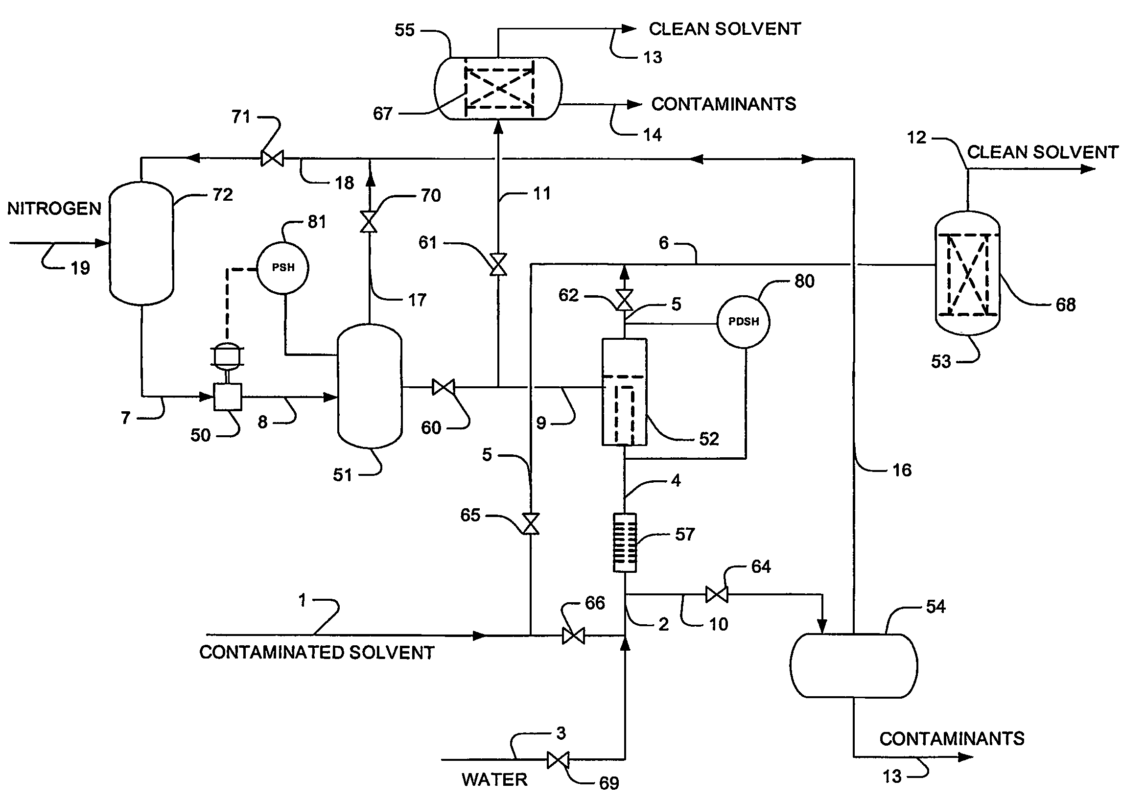
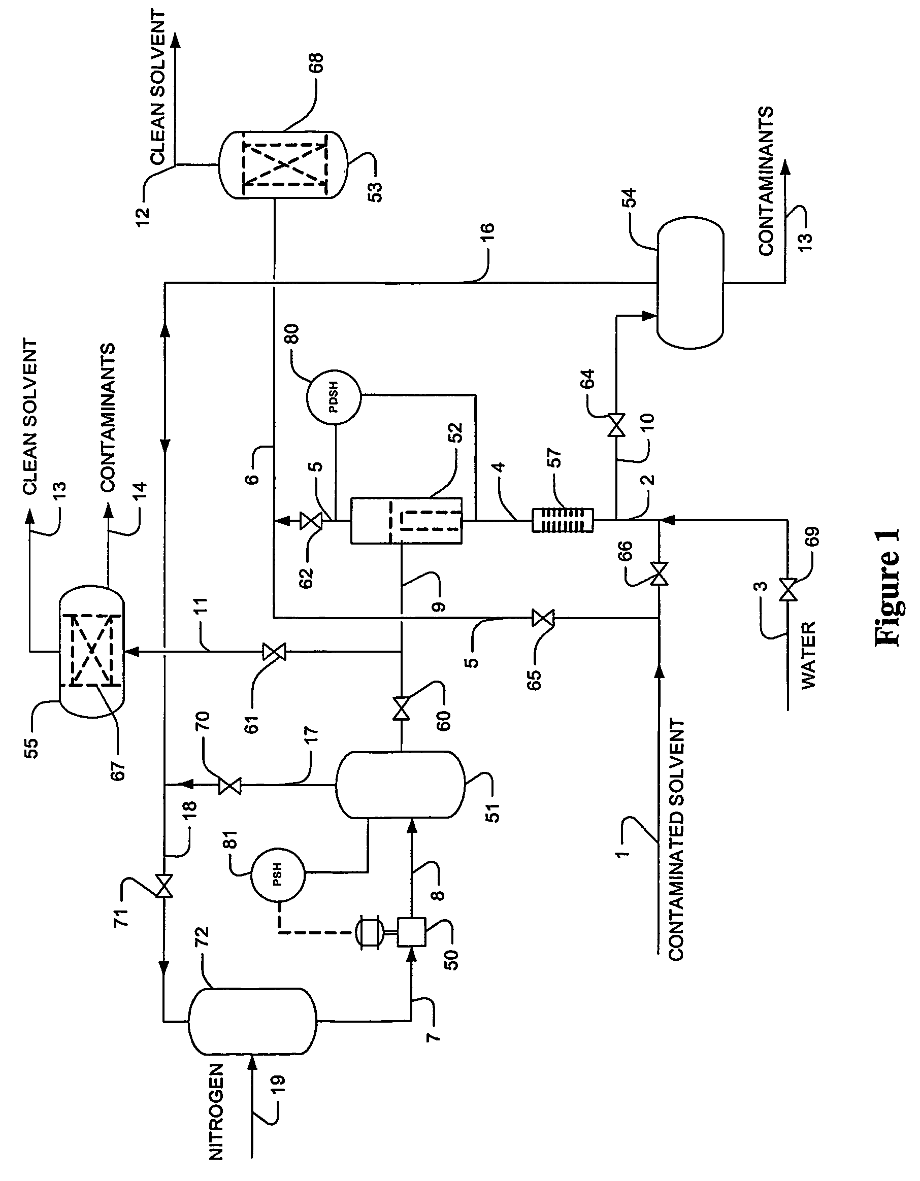
[0014]FIG. 1 depicts an exemplary filtration system comprising a prefilter 52, a main filter 53, a fluid source 3 that provides the fluid to purge solvent from the prefilter 52 during prefilter regeneration, a gas source 51 that provides the gas to purge particulates from the prefilter 52, and respective associated lines and valves to provide recycling circuits for the solvent, the fluid, and the gas. Together, these units are designed to remove particulates (e.g., nickel carbonyl, iron sulfides, nickel sulfide, and other corrosion products) and contaminants from a circulating solvent while preventing loss and / or emission of the solvent, fluid, and / or gas.

[0015]In filtering operation a portion of contaminated solvent is routed via line 1, valve 66, and line 2 to the prefilter 52 (optionally via electrostatic precipitator 57 and line 4), while valve 65 remains closed at that time. Partially filtered solvent stream 5 exits the prefilter 52 and is routed via valve 62 and line 6 to the ...


PUM

PropertyMeasurementUnit
differential pressureaaaaaaaaaa
differential pressuresaaaaaaaaaa

Abstract

A filter system has a first filter from which solvent is recovered in a cleaning cycle using a rinse fluid in forward flow, and from which particulates are removed using flush gas in reverse flow. At least part of the solvent and the flush gas are recycled to the system, and in still further preferred aspects, filtration of the solvent continues during the cleaning cycle via a bypass circuit through which the solvent is routed to a second filter.

Description

[0001]This application claims priority to U.S. provisional patent application with Ser. No. 60 / 519,531, which was filed Nov. 12, 2003, and which is incorporated by reference herein.FIELD OF THE INVENTION[0002]The field of the invention is relates generally to recirculating solvent filter systems.BACKGROUND OF THE INVENTION[0003]Flue gases contain numerous gaseous and solid contaminants. Gaseous contaminants include NOx, SOx, H2S, COS, and carbonyl. These gaseous contaminants are typically removed with a re-circulating solvent system, which can include MEA, DGA, DIPA, MDEA, propylene carbonate, tributyl phosphate, normal methyl pyrrolidone, as well as various polyethylene glycol dialkyl ethers. Mixtures of these solvents are also used, including for example, mixtures of dimethyl ethers of polyethylene glycols and water. Solvents are typically recirculated, with 10% to 20% of the circulating solvent commonly being filtered in a slip stream.[0004]Solid contaminants include calcium and ...

Claims


Application Information

Patent Timeline
Patent Type & Authority Patents(United States)
IPC IPC(8): B01D35/16B01D29/66B01D35/12B01D41/00
CPCB01D29/66B01D35/12
Inventor MAK, JOHNNIELSEN, RICHARD B.
Owner FLUOR TECH CORP
Why Eureka
Try Eureka