RF-switched superconducting resonators and methods of switching thereof

a superconducting resonator and superconducting technology, which is applied in the direction of reradiation, magnetic field measurement using superconducting devices, instruments, etc., can solve the problems of increasing the resistance and lowering the quality factor q of the multi-mode resonator, so as to reduce the q factor of the receiver resonator, increase the resistance, and reduce the q factor of the transmitter resonator

Inactive Publication Date: 2010-09-07
AGILENT TECH INC
View PDF7 Cites 4 Cited by
  • Summary
  • Abstract
  • Description
  • Claims
  • Application Information

AI Technical Summary

Benefits of technology

[0011]The present invention addresses these and other problems associated with the prior art and overcomes its limitations of using the NMR transmitter pulse to reduce the Q factor of the receiver resonator. The present invention also meets the needs to reduce the Q factor of the transmitter resonator after a transmit pulse or while receiving by employing a cryogenic multimode resonator that is coupled to a NMR spectrometer and to a RF switch power source. This multimode resonator resonates at two or more independent frequencies. The first resonant frequency corresponds to the NMR frequency of the spectrometer. Another resonant frequency corresponds to a frequency of the RF switch power source, which is generally higher in value than the first one. A RF switch made of HTS material forms a section of the cryogenic multimode resonator. Activation of the RF switch power source produces a current in the multimode resonator that approaches or exceeds the critical current of the RF switch, causing the superconducting material of the RF switch to become a non-superconducting thereby increasing its resistance and lowering the quality factor Q of the multimode resonator.

Problems solved by technology

Activation of the RF switch power source produces a current in the multimode resonator that approaches or exceeds the critical current of the RF switch, causing the superconducting material of the RF switch to become a non-superconducting thereby increasing its resistance and lowering the quality factor Q of the multimode resonator.

Method used


Image

  • RF-switched superconducting resonators and methods of switching thereof
  • RF-switched superconducting resonators and methods of switching thereof
  • RF-switched superconducting resonators and methods of switching thereof

Examples


Embodiment Construction

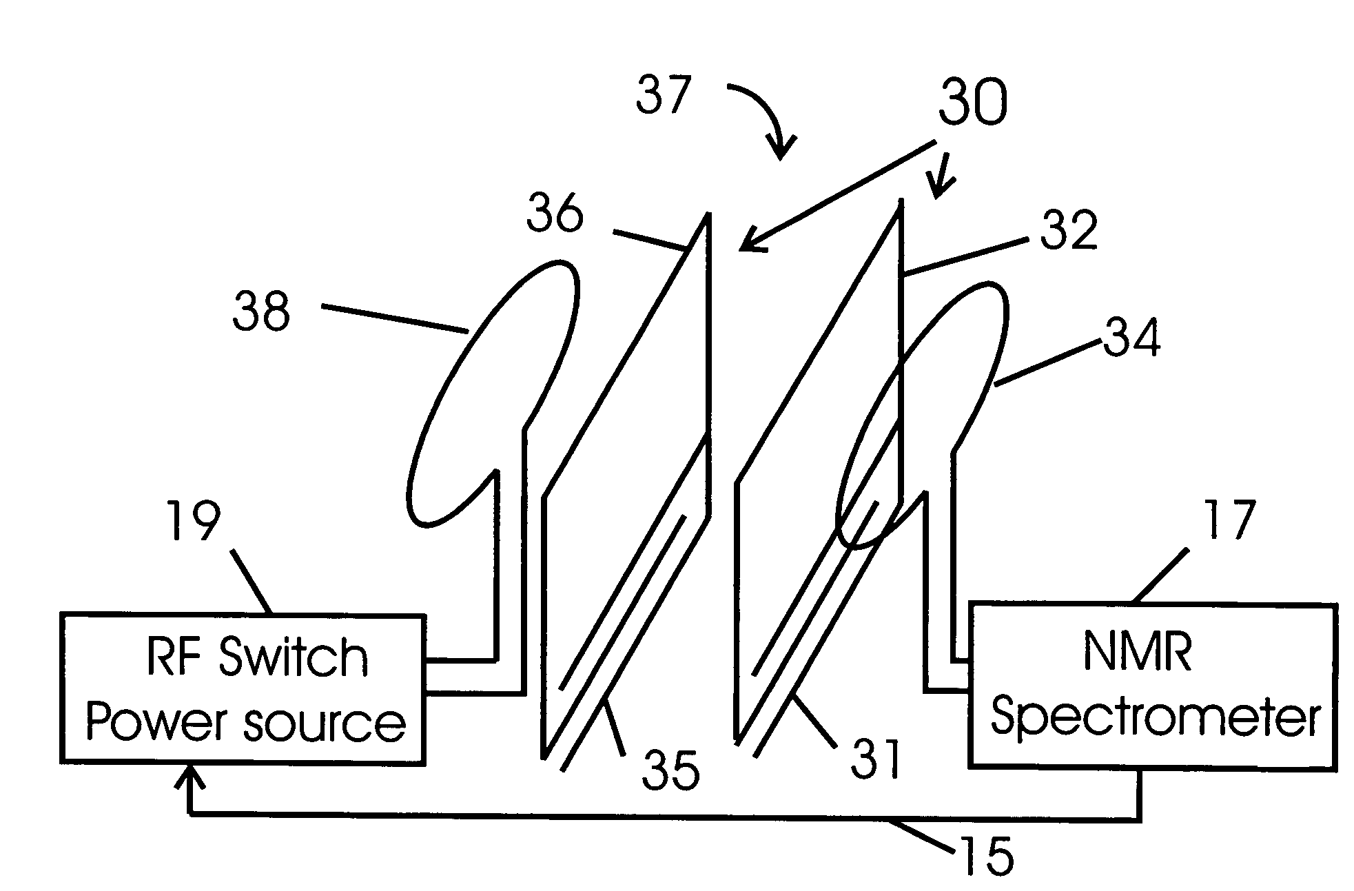
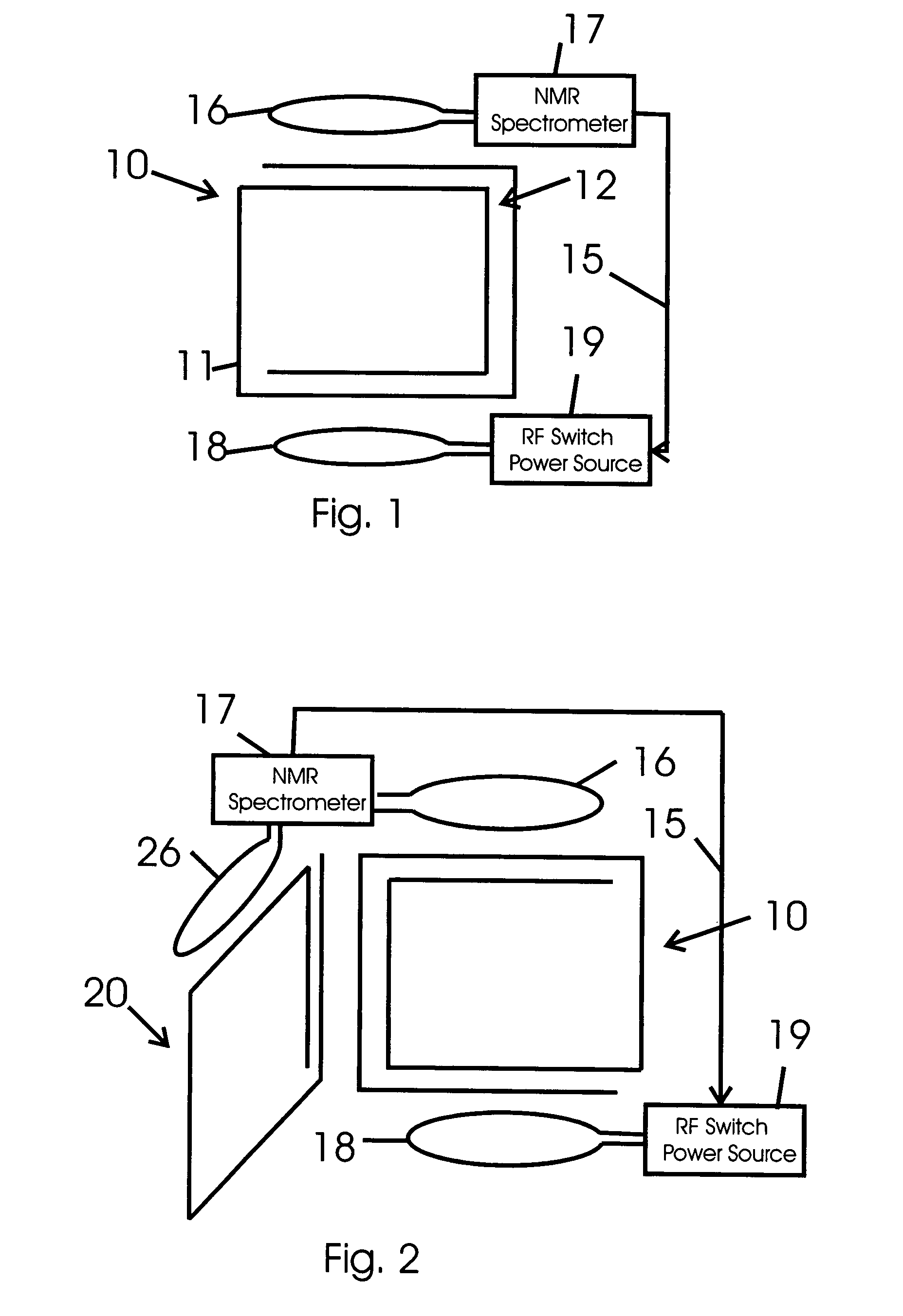
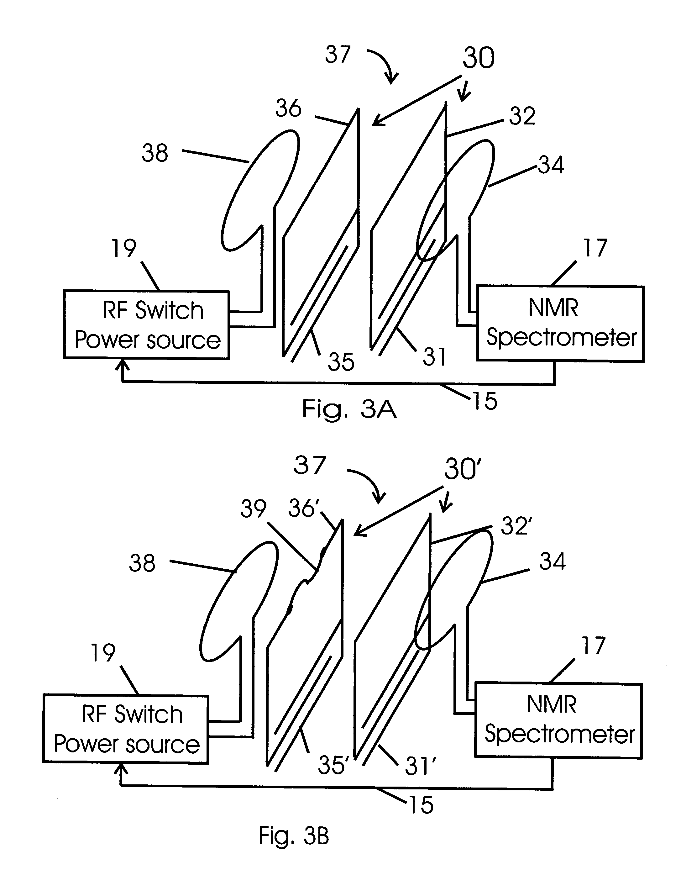
[0024]Turning to the drawings, FIG. 1 illustrates an exemplary RF coil of the NMR probe, which is a HTS multimode resonator 10, with distributed inductance and capacitance 12, resonates at a fundamental frequency and at one or more higher frequencies. As described below, other resonator configurations also may have more than one resonant frequency mode. Normally the lowest frequency mode is used for the NMR transmit and receive functions, and the higher frequency modes are ignored or tuned such that they do not perturb the NMR experiment. The HTS multimode resonator 10 is coupled to the NMR spectrometer 17 by coupling loop 16 and to an RF switch power source 19 by coupling loop 18. The RF frequency of the RF switch power source 19 is tuned to one of the higher frequency modes of resonator 10. The Q factor of HTS multimode resonator 10 is decreased by activating the RF switch power source 19 thereby inducing a RF current in the windings of resonator 10 that is approaching or above th...


PUM


Abstract

A multimode resonator resonating at two or more frequencies is operated at cryogenic temperatures and composed of a superconducting material or a normal metal with a superconducting section serving as a RF superconducting switch. The multimode resonator is coupled to a NMR spectrometer and a RF switch power source, wherein its one frequency is selected to correspond to the operating frequency of the NMR spectrometer and at least a second frequency is tuned to a frequency of RF switch power source, unrelated to the spectrometer frequency, therefore power at this frequency does not perturb the operation of the spectrometer. When activated, the RF switch power source induces a current sufficient to approach or exceeds the critical current in one or more sections of the superconducting material of the multimode resonator, thereby increasing its resistance and reducing the Q factor of the multimode resonator.

Description

FIELD OF THE INVENTION[0001]The present invention relates to nuclear magnetic resonance (NMR) technology utilizing radio frequency (RF) resonators fabricated from superconducting materials.BACKGROUND OF THE INVENTION[0002]A conventional NMR detection system uses a magnet, a probe and a spectrometer. The magnet polarizes the sample by producing a strong magnetic field in a sample region. Superconducting magnets produce the strongest magnetic fields, and operate at low temperatures requiring a Dewar and cryogenic equipment. The probe is positioned within the magnet and supports the sample and the RF coils or resonators generating and detecting the RF magnetic fields used to stimulate and detect the resonance signals from the nuclear spins. Probes with cryogenic resonators also contain a Dewar system and a temperature control system that maintains a very low temperature environment for these resonators and maintain a near room temperature environment for the sample. Cryogenic resonator...

Claims


Application Information

Patent Timeline
Patent Type & Authority Patents(United States)
IPC IPC(8): G01V3/00
CPCG01R33/34023G01R33/3657G01R33/035G01R33/34053G01R33/34061G01R33/34092G01R33/341G01R33/3642G01R33/3671
Inventor WONG, WAI HAWITHERS, RICHARD STACYANDERSON, WESTON A.
Owner AGILENT TECH INC
Why Eureka
Try Eureka