DC-DC flyback converter having a synchronous rectification self-driven circuit

a self-driven, synchronous technology, applied in the direction of dc-dc conversion, power conversion systems, climate sustainability, etc., can solve the problems of limited application of some self-driven converters, permanent damage to srb>1/b> or srb>2, and the complexity of existing self-driven circuits is often too complex to be widely adopted in practical applications, etc., to achieve simple structure, reduce cross conduction loss, and reduce cost

Inactive Publication Date: 2010-09-07
YIBO POWER SUPPLY CO LTD HANGZHOU
View PDF3 Cites 89 Cited by
  • Summary
  • Abstract
  • Description
  • Claims
  • Application Information

AI Technical Summary

Benefits of technology

[0006]The object of the present invention is to solve the foregoing and other issues with the self-driven technology commonly used in existing flyback converters, by providing a DC-DC converter having a self-driven circuit which enables a transformer with simpler structure, lower cost and lower cross conduction loss to be used and which is particularly suitable for a self-driven circuit with multiple outputs, and without negative voltage between the synchronous rectifier's gate and source.
[0007]The present invention uses some low power R, C components, diodes, b-polar transistors and MOSFETs to implement the equivalent self-driven technology for synchronous rectifiers. Such a technology guarantees reliable switch-on and switch-off of the synchronous rectifiers and reduces the loss of cross conduction to a minimum, thus achieving higher efficiency when it is used in low voltage, high current applications.

Problems solved by technology

However, the conduction loss of the Schottky diode with a forward conduction voltage of approximately 0.3V has become a bottleneck in miniaturizing these converters and in improving their thermal performance.
But for flyback converters, existing self-driven circuits are often too complex to be widely adopted in practical applications.
Meanwhile, the application of some self-driven converters is greatly restricted because of difficulties in controlling the cross conduction, or the driver voltage between the gate and source of the synchronous rectifier MOSFET.
This negative voltage is in direct ratio to Vin and will ramp up significantly when Vin is high, and, in the worst case, will result in permanent damage to S1 or SR2.
Even if the converter functions properly, it will be hard to improve the efficiency of the converter because the loss in the driven circuit of the synchronous rectifier will be greatly increased as the input voltage increases.
This will make it hard to achieve high power density.
On the occasions, where high voltage isolation is required for the primary and secondary windings, such a self-driven circuit will cause hindrance to the isolation.
Meanwhile, because there is high leakage inductance of the self-driven transformer under this circumstances, the voltage spike of the drive wave transmitted to the secondary winding will be very high, which is very likely to break down the gate of the synchronous rectifier.

Method used


Image

  • DC-DC flyback converter having a synchronous rectification self-driven circuit
  • DC-DC flyback converter having a synchronous rectification self-driven circuit
  • DC-DC flyback converter having a synchronous rectification self-driven circuit

Examples


Embodiment Construction

)

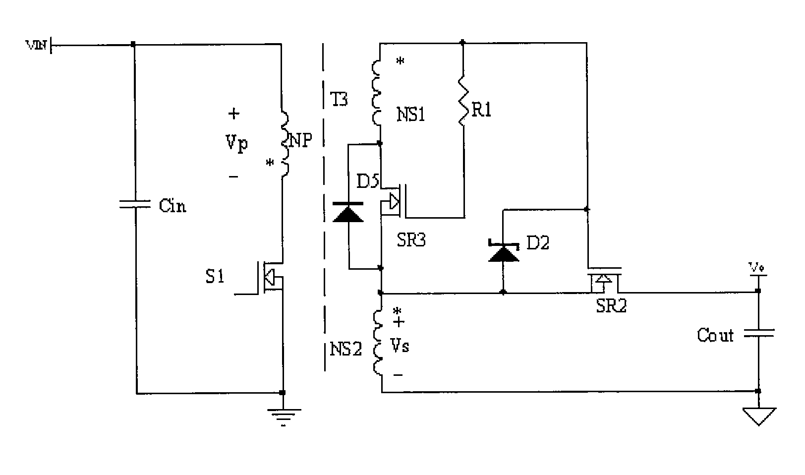
[0026]Referring to FIG. 3(a), a flyback converter employing the first type of self-driven circuit for the synchronous rectifier in accordance with the present invention includes a primary power circuit, a secondary power circuit and a self-driven circuit. The primary power circuit includes a main power MOSFET S1, a primary winding NP of the transformer and an input capacitor Cin. The secondary power circuit includes a secondary winding NS2 of the transformer, a rectifier SR2 and an output capacitor Cout. The self-driven circuit mainly consists of a negative voltage removal circuit and a synchronous rectifier trigger switch-off circuit. The negative voltage removal circuit is formed by an N channel MOSFET SR3 and a resistor R1, while the synchronous rectifier trigger switch-off circuit is made up of MOSFET SR3, winding NS1 and Zener diode D2. The drive voltage of the synchronous rectifier is mainly generated by adjusting the turns ratio of NS1 and NS2. In the negative voltage remova...


PUM


Abstract

A DC-DC flyback converter, includes a three-winding transformer; a primary power circuit having a first MOSFET connected to a first winding of the transformer; a secondary power circuit connected to a second winding of the transformer terminals; and a self-driven circuit connected to a third winding of the transformer. The secondary power circuit includes a synchronous rectifier in the form of a second MOSFET and the self-driven circuit further includes a delay drive circuit, an isolation differential circuit, a negative removal circuit having a third MOSFET and a synchronous rectifier trigger switch-off circuit for switching the synchronous rectifier to an off condition.

Description

FIELD OF THE INVENTION[0001]The present invention relates to high power density power supplies with high current and low output voltage. More specifically, it relates to flyback DC-DC converters having novel synchronous rectification self-driven circuits.BACKGROUND OF THE INVENTION[0002]With the rapid development of semiconductors and ultra large-scale IC, the demand for low cost isolated dc-dc converters with high current and low voltage has increased greatly. However, the conduction loss of the Schottky diode with a forward conduction voltage of approximately 0.3V has become a bottleneck in miniaturizing these converters and in improving their thermal performance. Output synchronous rectification has proven to be the only way to enhance the converter's reliability. While the gate of the synchronous rectifier needs to be oscillated by a corresponding drive circuit, the control of the drive circuit normally requires very good sequencing to prevent the cross conduction between a prim...

Claims


Application Information

Patent Timeline
Patent Type & Authority Patents(United States)
IPC IPC(8): H02M3/335
CPCH02M3/33592Y02B70/1475Y02B70/10
Inventor ZHANG, CONGFENGZHANG, HAOHUA, GUICHAO
Owner YIBO POWER SUPPLY CO LTD HANGZHOU
Why Eureka
Try Eureka