Composite cavity for enhanced efficiency of up-conversion

a composite cavity and efficiency technology, applied in the field of composite cavity for enhanced efficiency of up-conversion, can solve the problems of poor contrast, difficult to view lcds in low ambient light environments, complicated manufacturing, etc., and achieve the effect of greatly improving up-conversion based displays and improving up-conversion efficiency

Active Publication Date: 2010-09-28
UNIV OF CENT FLORIDA RES FOUND INC
View PDF28 Cites 27 Cited by
  • Summary
  • Abstract
  • Description
  • Claims
  • Application Information

AI Technical Summary

Benefits of technology

[0017]A primary objective of the invention is to provide methods, apparatus and systems for up-converting materials that absorb infrared light and emit visible light placed within a composite cavity for improved up-conversion efficiency and enabling greatly improved up-conversion based displays.
[0018]A second objective of the invention is to provide methods, apparatus and systems to prepare a composite cavity for up-converting materials, in order to both enhance the absorption of pump light and to improve the emission of the visible light for improved up-conversion efficiency.
[0019]A third objective of the invention is to provide methods, apparatus and systems for composite cavities that increase the efficiency of visible light emission from up-converters by placing them in the composite cavities which can enhance the absorption of incident pump light, or the emission of the desired visible light or both.

Problems solved by technology

However, LCDs have suffered from several problems over the years.
For example, LCDs are difficult to view in low ambient light environments and have a limited viewing angle and poor contrast.
The Hunter patents describe liquid crystal displays that require arranging individual pixels in rows and corresponding columns which can be expensive, complicated to manufacture, and have narrow angular view ranges with low brightness.
However, for the single display media, Downing '403 uses nanometer sized particles which would inherently be difficult to form, handle and disperse in a display medium.
However, these patents also fail to overcome the problems with the other patents described above.
One light source can generate three colors with a low limit efficiency.
The efficiency that was observed or expected for this process was low in singly doped media.
However, because no powerful source existed in the 980-nm region in order to excite those up-converters, no practical product came out of the research.
It has been noticed in the prior art that pumping conditions caused heating of the material and that higher efficiencies were obtained with low duty cycle excitation.
A problem with prior art up-conversion devices is limited efficiency since much of the incident pump light is back scattered by the up-converting particles and does not get used to generate visible light.

Method used


Image

  • Composite cavity for enhanced efficiency of up-conversion
  • Composite cavity for enhanced efficiency of up-conversion
  • Composite cavity for enhanced efficiency of up-conversion

Examples


Embodiment Construction

[0053]Before explaining the disclosed embodiments of the present invention in detail it is to be understood that the invention is not limited in its application to the details of the particular arrangements shown since the invention is capable of other embodiments. Also, the terminology used herein is for the purpose of description and not of limitation.

[0054]The following is a list of the reference numbers used in the drawings and the detailed specification to identify components:

[0055]

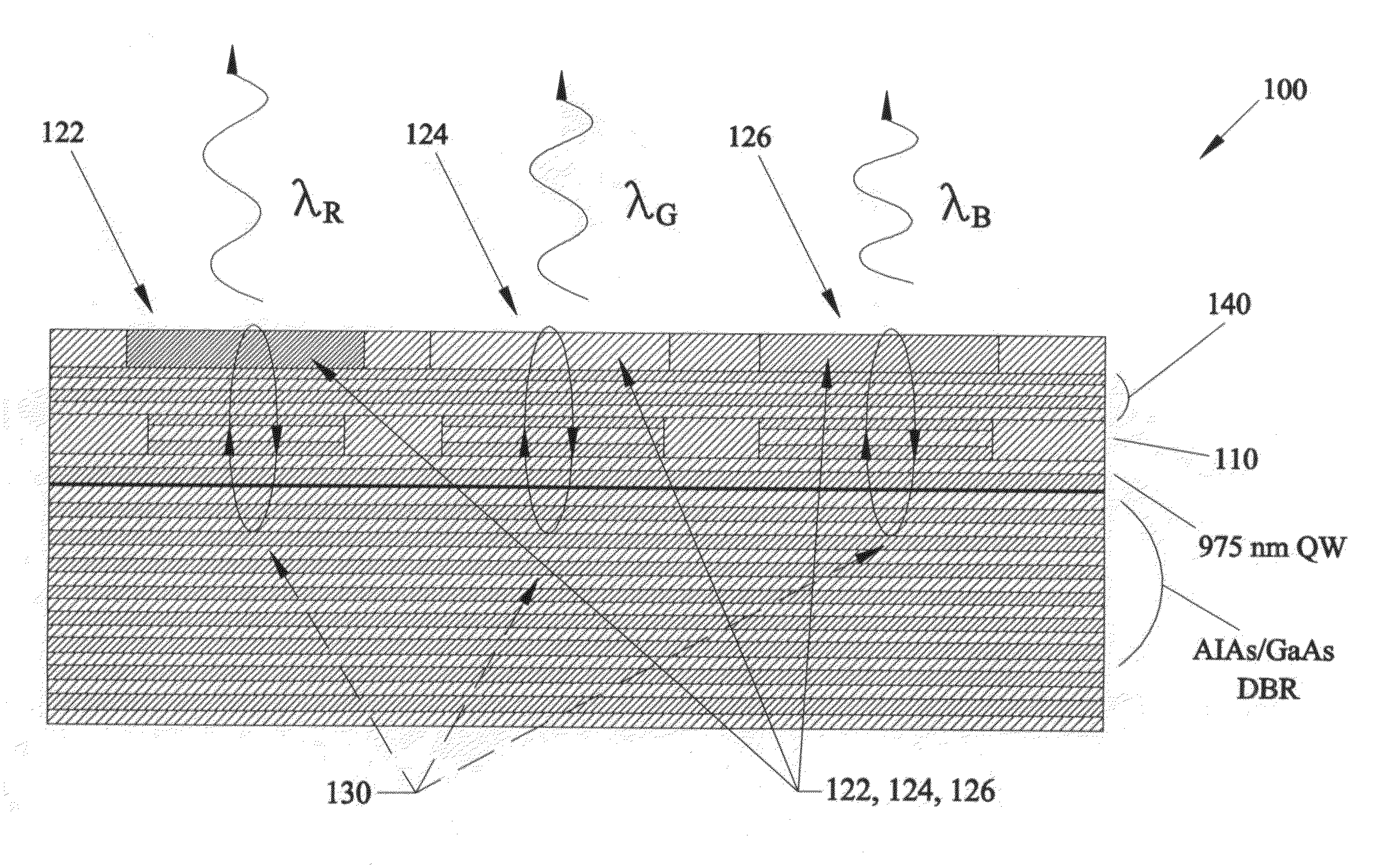
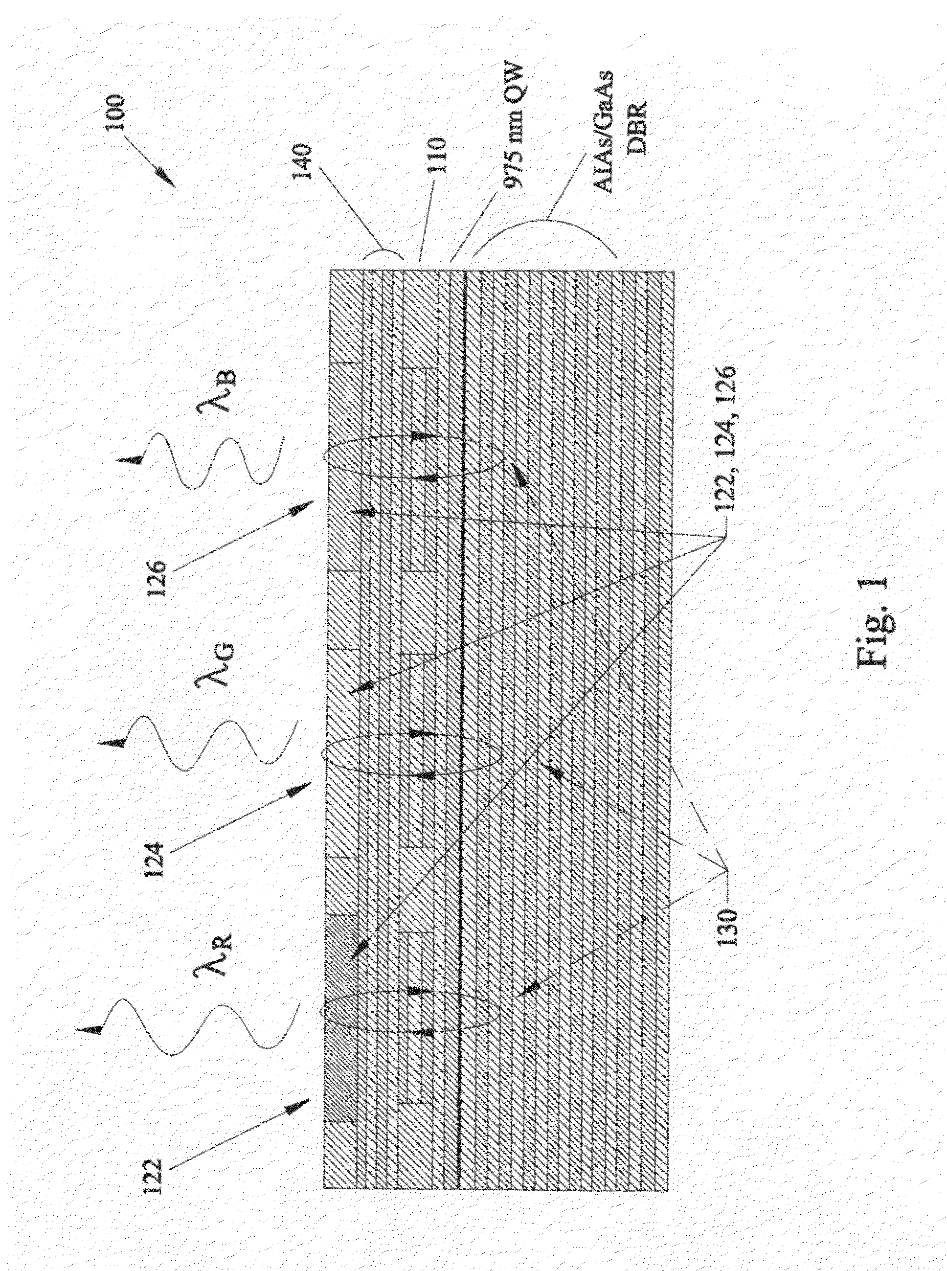
100RGB pixel110RCLED122red up-converter124green up-converter126blue up-converter130surface emitter140RGB mirror200UC / RCLED pixel array220RCLED300pixel322red up-converter324green up-converter326blue up-converter400pixel410column electrodes415row electrodes430column isolations435row isolations500optical system510beam splitter512green beam514red beam520absorber530beam splitter534blue beam

[0056]Prior art up-conversion patents include U.S. Pat. No. 5,089,860 issued to Deppe et al. on Feb. 18, 1992, U.S. P...


PUM


Abstract

Methods, apparatus and systems for an up-converter resonant cavity light emitting diode device includes a semiconductor light source, an up-converter to form the light emitter with up-converting materials and an electrical source coupled with the semiconductor light source for providing electrical energy to the semiconductor light source to provide a desired wavelength emitted light. The semiconductor light source is a resonant cavity light emitting diode or laser that emits an approximately 975 nm wavelength to provide electrical and optical confinement to the semiconductor light source to form a resonant cavity up-converting light emitting diode (UC / RCLED). Rows and columns of electrodes provide active matrix addressing of plural sets of UC / RCLEDs for display devices. The up-converter resonant cavity light emitting diode device has applications in head mounted projection display optical system using spectrally selective beam splitters to eliminate spectral overlap between colors and to combine the red, green and blue beams.

Description

[0001]This application claims the benefit of priority to U.S. Provisional Patent Application Nos. 61 / 026,827 filed on Feb. 7, 2008, U.S. Provisional Patent Application No. 60 / 939,924 filed on May 24, 2007 and U.S. Provisional Application No. 60 / 939,956 filed on May 24, 2007.FIELD OF THE INVENTION[0002]This invention relates to up-conversion efficiency and, in particular, to methods, systems, apparatus and devices for up-conversion materials that absorbs infrared light and emits visible light, with the materials placed within a composite cavity for improved up-conversion efficiency and for enabling greatly improved up-conversion based displays including headset displays for virtual reality and three-dimensional imaging.BACKGROUND AND PRIOR ART[0003]Liquid crystal displays LCDs have been popular for many applications, primarily in low power areas such as battery-powered systems or small size applications. However, LCDs have suffered from several problems over the years. For example, L...

Claims


Application Information

Patent Timeline
Patent Type & Authority Patents(United States)
IPC IPC(8): G02B27/14H01L29/06H01L21/02H01L33/00
CPCG02B27/017G02B2027/0112G02B2027/0118H01L27/153H01L33/50
Inventor BASS, MICHAELDEPPE, DENNIS G.
Owner UNIV OF CENT FLORIDA RES FOUND INC
Why Eureka
Try Eureka