

Controlled synthesis of nanoparticles using continuous liquid-flow aerosol method
a technology of aerosol and nanoparticles, which is applied in the direction of silve compounds, copper oxides/halides, and magnesium oxides/halides, etc., can solve the problems of inability to generate reproducible results from one, large product size distribution, and low boiling point, and achieves easy synthesis and synthesis. high, high quality
- Summary
- Abstract
- Description
- Claims
- Application Information
AI Technical Summary
Benefits of technology
Problems solved by technology
Method used
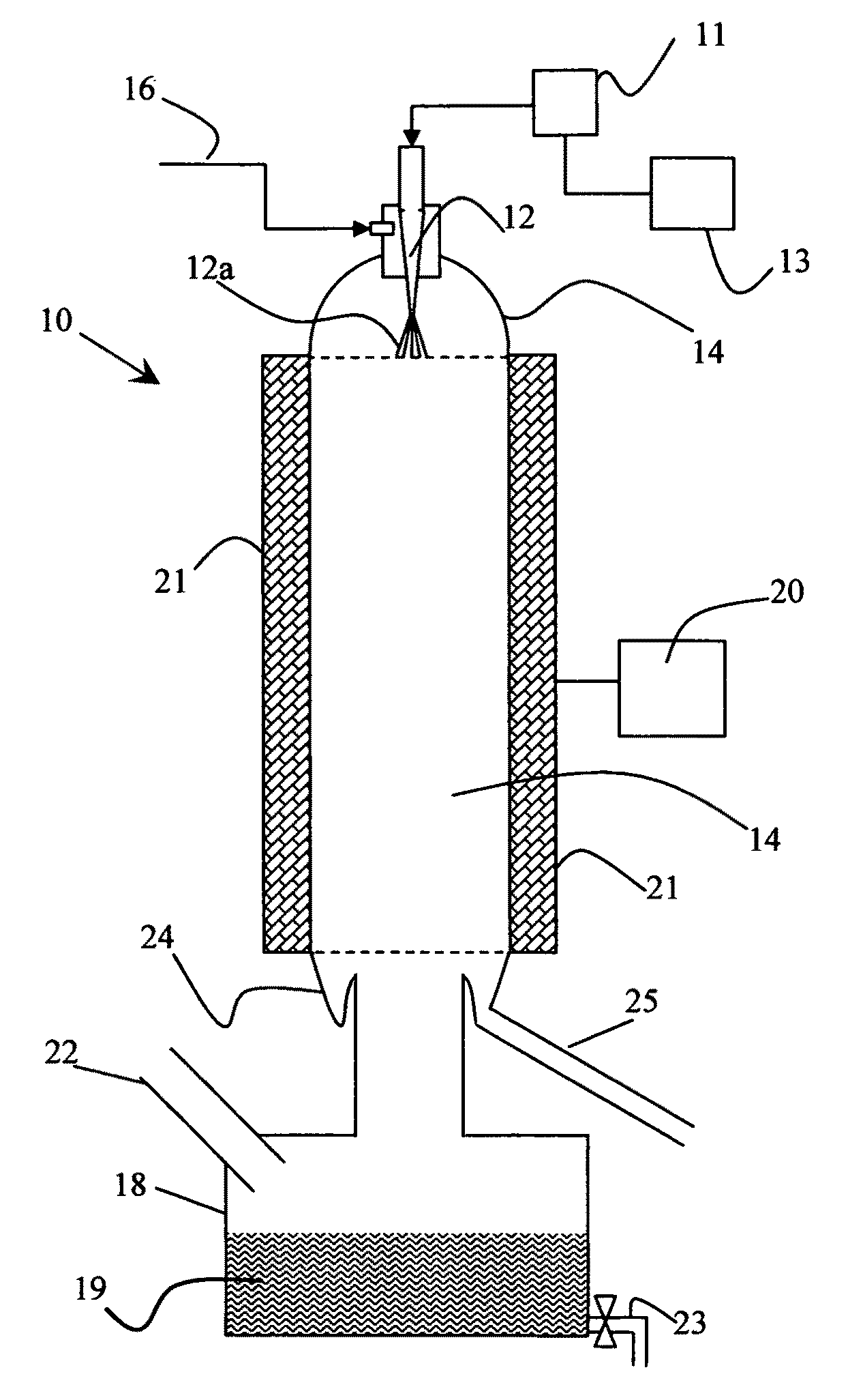
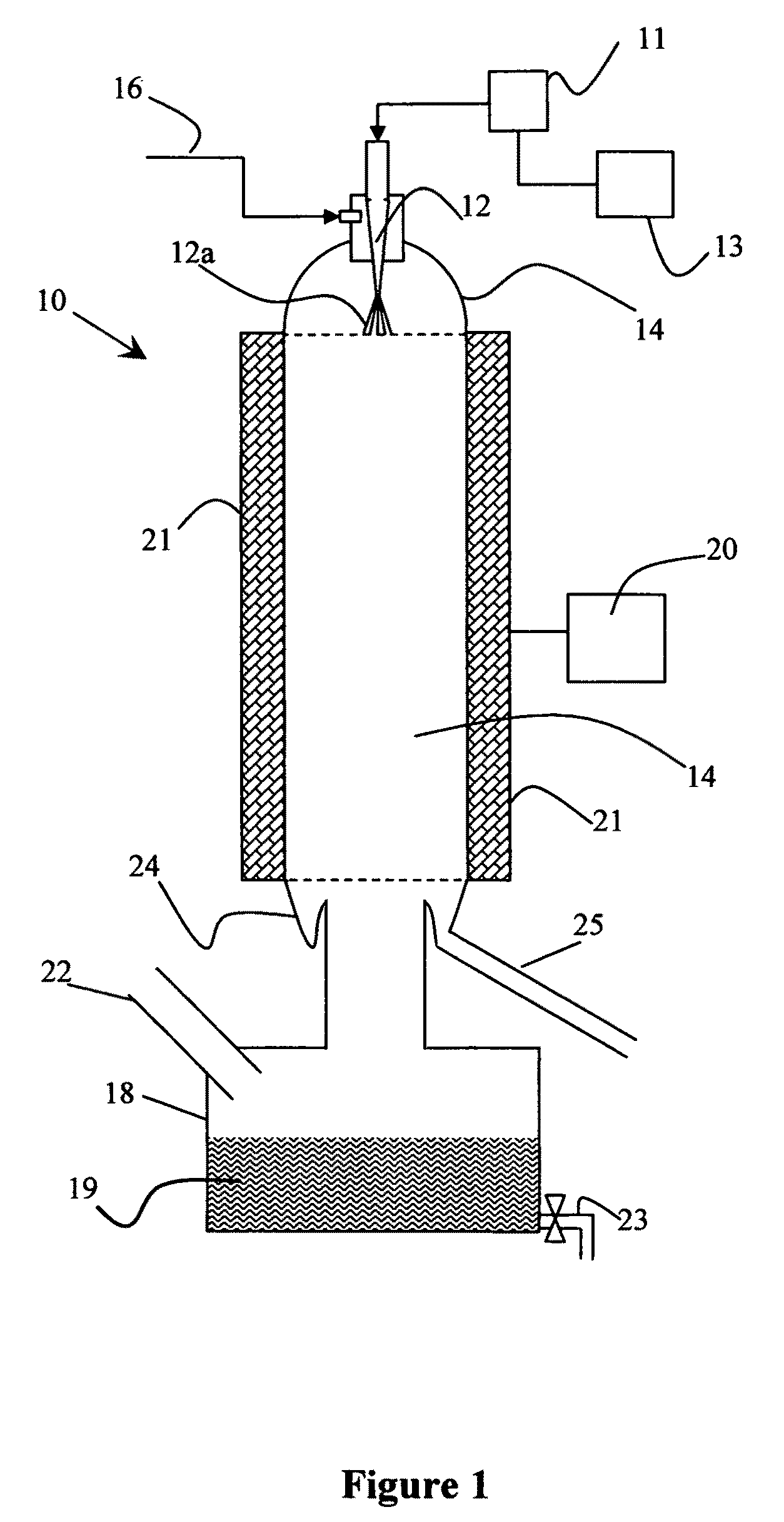
Image

Examples
examples
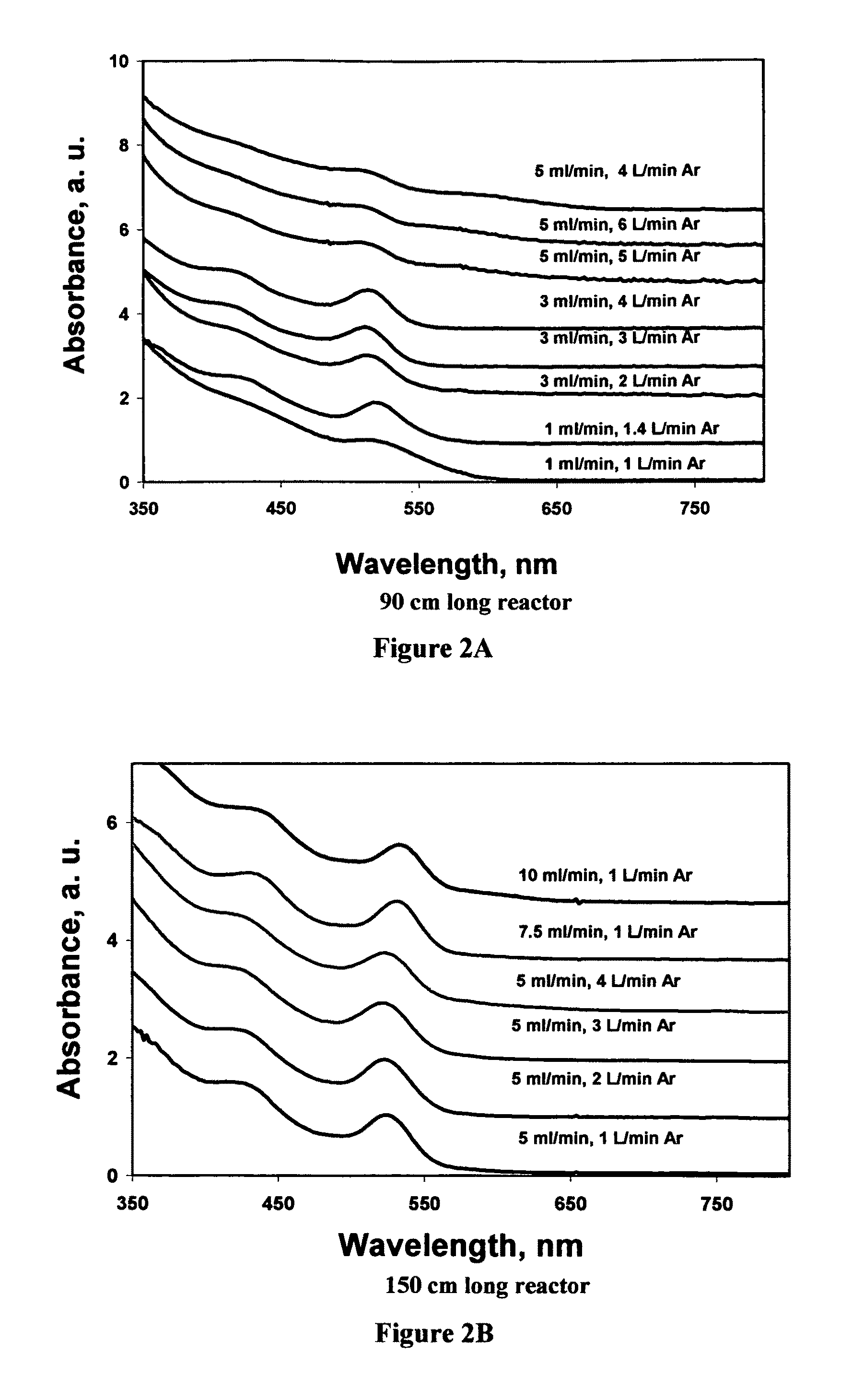
[0041]Synthesis of cadmium chalcogenides from organic solutions can be achieved in accordance with the invention. One of the first targets was the synthesis of cadmium selenide nanoparticles. The advantage of CdSe nanocrystals over other nanocrystals is that the particle fluorescence covers the whole visible region, so it potentially can be used as a light emitting diode, in solar cells or as a multi-wavelength fluorescent probe (See S. Coe, W.-K. Woo, M. Bawendi, V. Bulovic (2002), “Electroluminescence from single monolayers of nanocrystals in molecular organic devices,” Nature, 420: 800-803; I. Gur, N. A. Fromer, M. L. Geier, A. P. Alivisatos (2005), “Air-Stable All-Inorganic Nanocrystal Solar Cells Processed from Solution,” Science, 310: 462-466; D. Larson et al (2003), “Water-soluble quantum dots for multiphoton fluorescence imaging in vivo,” Science (Washington D.C.) 300: 1434-1436).
[0042]The synthesis of CdSe nanocrystals from organic solutions initially used a mixture of trio...
PUM
| Property | Measurement | Unit |
|---|---|---|
| diameter | aaaaa | aaaaa |
| diameter | aaaaa | aaaaa |
| width half | aaaaa | aaaaa |
Abstract
Description
Claims
Application Information