Mechanically tunable elastomeric optofluidic distributed feedback dye lasers

a distributed feedback and optofluidic technology, applied in lasers, laser details, active medium materials, etc., can solve the problems of unfavorable dye selection and dye concentration, microfluidic laser wavelength tuning, and undetectable simultaneous multiple modes of operation and wide emission line widths

Inactive Publication Date: 2010-10-19
CALIFORNIA INST OF TECH
View PDF6 Cites 6 Cited by
  • Summary
  • Abstract
  • Description
  • Claims
  • Application Information

AI Technical Summary

Problems solved by technology

A number of problems in the above microfluidic lasers have been observed.
For example, because of the lack of both transverse mode and longitudinal mode selection, there can be undesired simultaneous multiple modes of operation and wide emission line widths.
Another problem is that microfluidic laser wavelength tuning has been limited to dye selection and dye concentration, which require relatively complex fluidics apparatus, including valves for porting various types of dye solutions and for varying the dye concentration and index of refraction methods related to the selection of fabrication materials.

Method used


Image

  • Mechanically tunable elastomeric optofluidic distributed feedback dye lasers
  • Mechanically tunable elastomeric optofluidic distributed feedback dye lasers
  • Mechanically tunable elastomeric optofluidic distributed feedback dye lasers

Examples


example 1

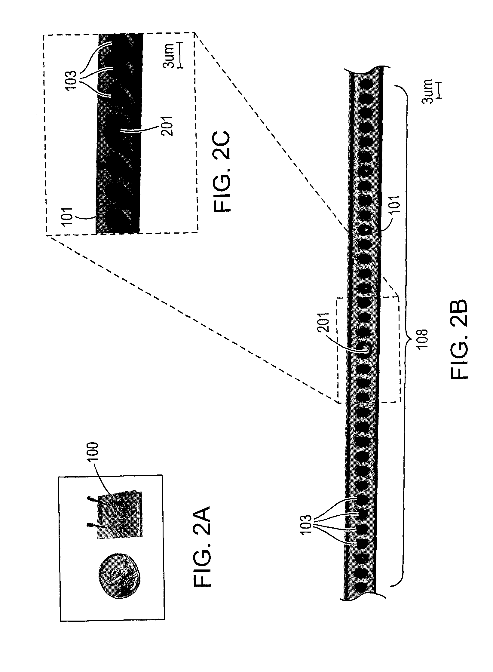
[0059]Briefly, a master mold was fabricated using conventional photolithography. 2 um thick SU8-2002 negative photoresist (available from the MicroChem. Corp. of Newton, Mass.) was spin-coated on a silicon wafer and patterned with a Cr-on-glass mask. The mold was treated with trimethylchlorosilane (available from the Sigma-Aldrich Co. of St. Louis, Mo.) for 3 min before use to facilitate the release of PDMS. Then 5:1 part A:B PDMS prepolymer (GE RTV 615, General Electric (“GE”) Sealants RTV Products-Elastomers) was poured onto the mold and baked at 80° C. for 30 min. The partially cured PDMS was peeled from the master and the liquid inlet and outlet ports were punched through the whole layer using a 23-gauge luer-stub adapter. The patterned PDMS, containing the laser structure, was then treated with oxygen plasma and bonded to another featureless PDMS to form a monolithic device. Finally, the resulting device was cut to size and baked overnight at 80° C. FIG. 2A shows an illustratio...

example 2

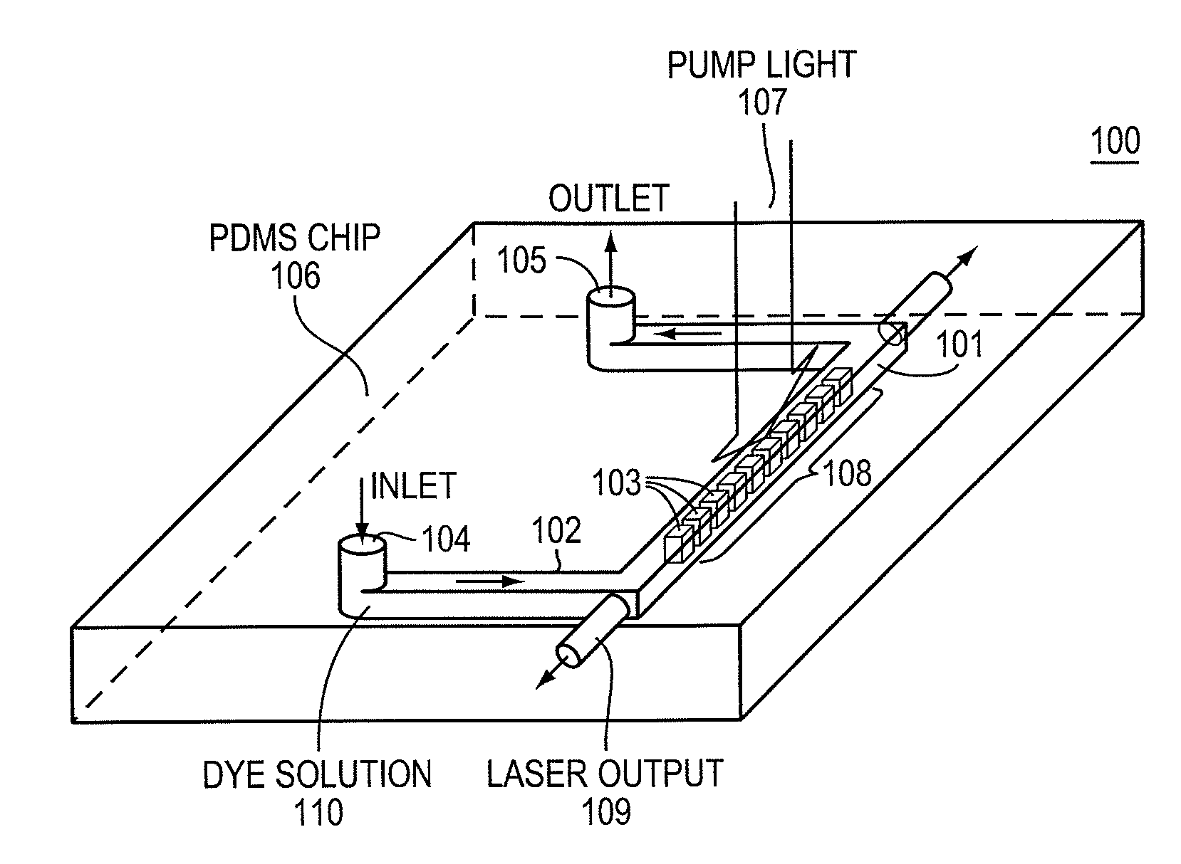
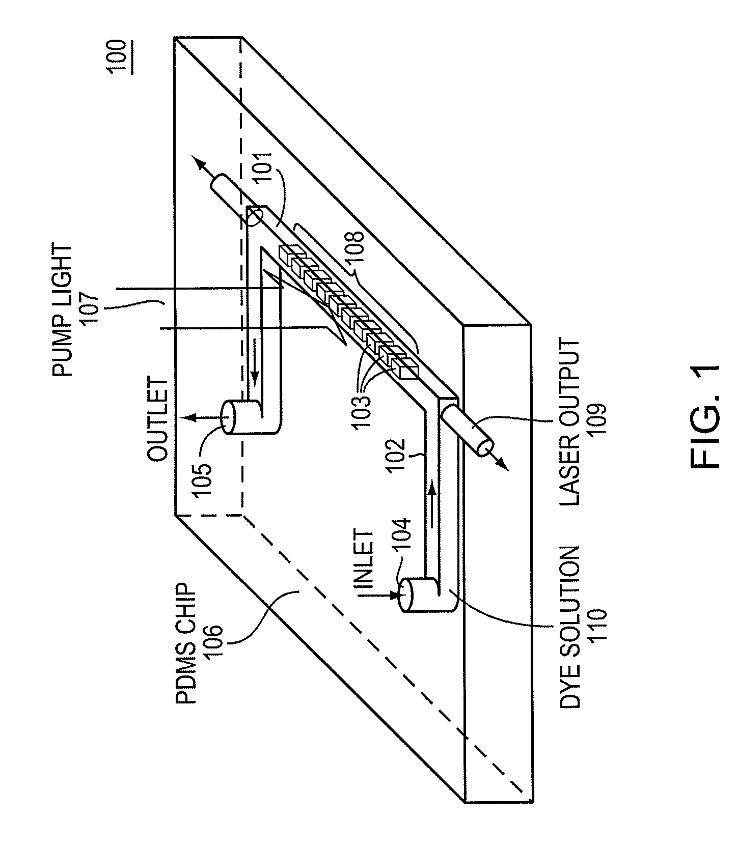
[0061]A microfluidic dye laser of the type shown in FIG. 1 was fabricated and tested. The optical waveguide dimensions (width 5 μm; height 2 μm) were chosen such that when filled with liquid of refractive index 1.409, the waveguide supported only the two fundamental E11 modes. If we define the x direction along the width and the y direction along the height, the E11x mode (transverse E field along x direction, considered to be TE-like) is more confined than the E11y mode, and thus is the preferred lasing mode. The small cross-section area not only reduces the required pump power to achieve the lasing threshold but also resulted in an extremely small consumption of dye solution (less than 40 picoliter per channel per fill).

[0062]To obtain stable single frequency operation, the free spectral range (“FSR”) of the employed cavity structure has to be larger than the gain spectral bandwidth. Organic dye molecules are well known to have very broad gain spectra with a typical bandwidth of 3...

example 3

[0068]A dye solution was introduced into the microfluidic channel of the microfluidic laser of example 2, by applying 10 psi pressure at an inlet port. It was found that to operate the laser in the pulsed mode that it was not necessary to circulate the dye solution, although continuous circulation of the dye solution did increase the output power. The laser chip was optically pumped with 6 ns Q-switched Nd:YAG laser pulses of 532 nm wavelength, focused to a ˜100 μm wide stripe aligned with the microfluidic channel. A 10× microscope objective was used to collect the emission light from one edge of the chip and deliver the emission light to a fiber coupled CCD-array based spectrometer, Ocean Optics model no. HR4000 having a 0.1 nm resolution (manufactured by Ocean Optics, Inc. of Dunedin, Fla.). A typical single mode lasing spectrum is shown in FIG. 4 where the lasing wavelength is 567.3 nm, very close to the predicted value 563 nm. The measured linewidth (inset “A”) is 0.21 nm. A plo...


PUM


Abstract

The invention relates to a microfluidic dye laser including a pump light source configured to provide light having a pump light wavelength. The microfluidic dye laser also includes an elastomer substantially optically transparent at the pump light wavelength and at a microfluidic dye laser wavelength. A microfluidic channel configured to accept a fluidic dye is defined in the elastomer. An optical grating is formed in a single mode 3D waveguide in the microfluidic channel in order to provide a single mode microfluidic dye laser light as output in response to illumination with light from the pump light source. In another aspect, the invention features a method of tuning a wavelength of a microfluidic dye laser light by mechanically deforming the elastomeric laser chip to change the grating period in the optical cavity.

Description

CROSS-REFERENCE TO RELATED APPLICATIONS[0001]This application claims priority to and the benefit of U.S. provisional patent application Ser. No. 60 / 837,177, filed Aug. 11, 2006, which application is incorporated herein by reference in its entirety.STATEMENT REGARDING FEDERALLY FUNDED RESEARCH OR DEVELOPMENT[0002]The invention described herein was made in the performance of work under a DARPA contract HR0011-04-1-0032, and is subject to the provisions of Public Law 96-517 (35 U.S.C. §202) in which the Contractor has elected to retain title.FIELD OF THE INVENTION[0003]The invention relates to optofluidic lasers in general and particularly to a microfluidic laser that employs wavelength tuning and transverse and longitudinal mode selection.BACKGROUND OF THE INVENTION[0004]There is a growing interest in small optofluidic (microfluidic) dye lasers. Microfluidic dye lasers can provide laser light for an optical system on a chip (“SOC”) or otherwise function as a compact laser light source...

Claims


Application Information

Patent Timeline
Patent Type & Authority Patents(United States)
IPC IPC(8): H01S3/20
CPCH01S3/022H01S3/213H01S3/08036H01S3/1053H01S3/1055
Inventor LI, ZHENYUPSALTIS, DEMETRISCHERER, AXELZHANG, ZHAOYU
Owner CALIFORNIA INST OF TECH
Why Eureka
Try Eureka