Magnetic field sensor circuit

a sensor circuit and magnetic field technology, applied in the field of magnetic field sensor circuits, can solve problems such as inability to perform optimally and field sensor circuits, and achieve the effect of improving performan

Inactive Publication Date: 2010-10-26
TITAN INTELLIGENCE TECH LTD
View PDF19 Cites 22 Cited by
  • Summary
  • Abstract
  • Description
  • Claims
  • Application Information

AI Technical Summary

Benefits of technology

[0009]It is an object of the invention to provide a magnetic field sensor circuit which has an improved performance in the presence of disturbing EM radiation.
[0016]In an embodiment, the first magneto-resistive sensor is a first magneto-resistive element and the second magneto-resistive sensor is a second magneto-resistive element. A first current source supplies a first current to the first magneto-resistive element to obtain the first sense signal across the first magneto-resistive element. A second current source supplies a second current to the second magneto-resistive element to obtain the second sense signal across the second magneto-resistive element. Thus, instead of two Wheatstone bridges of each four magneto-resistive elements, now only two magneto-resistive elements are required. This has the advantage that considerably less space is required for the sensor, which is particularly relevant in mobile applications. It has to be noted that in the full Wheatstone bridge configuration with a particular sensor area, the sensed voltage is about twice as high as across a single magneto-resistive element with one quarter of the particular area.

Problems solved by technology

The prior art magnetic field sensor circuit has the drawback that it does not perform optimally when a disturbing EM (Electro-Magnetic) radiation is present.

Method used


Image

  • Magnetic field sensor circuit
  • Magnetic field sensor circuit
  • Magnetic field sensor circuit

Examples


Embodiment Construction

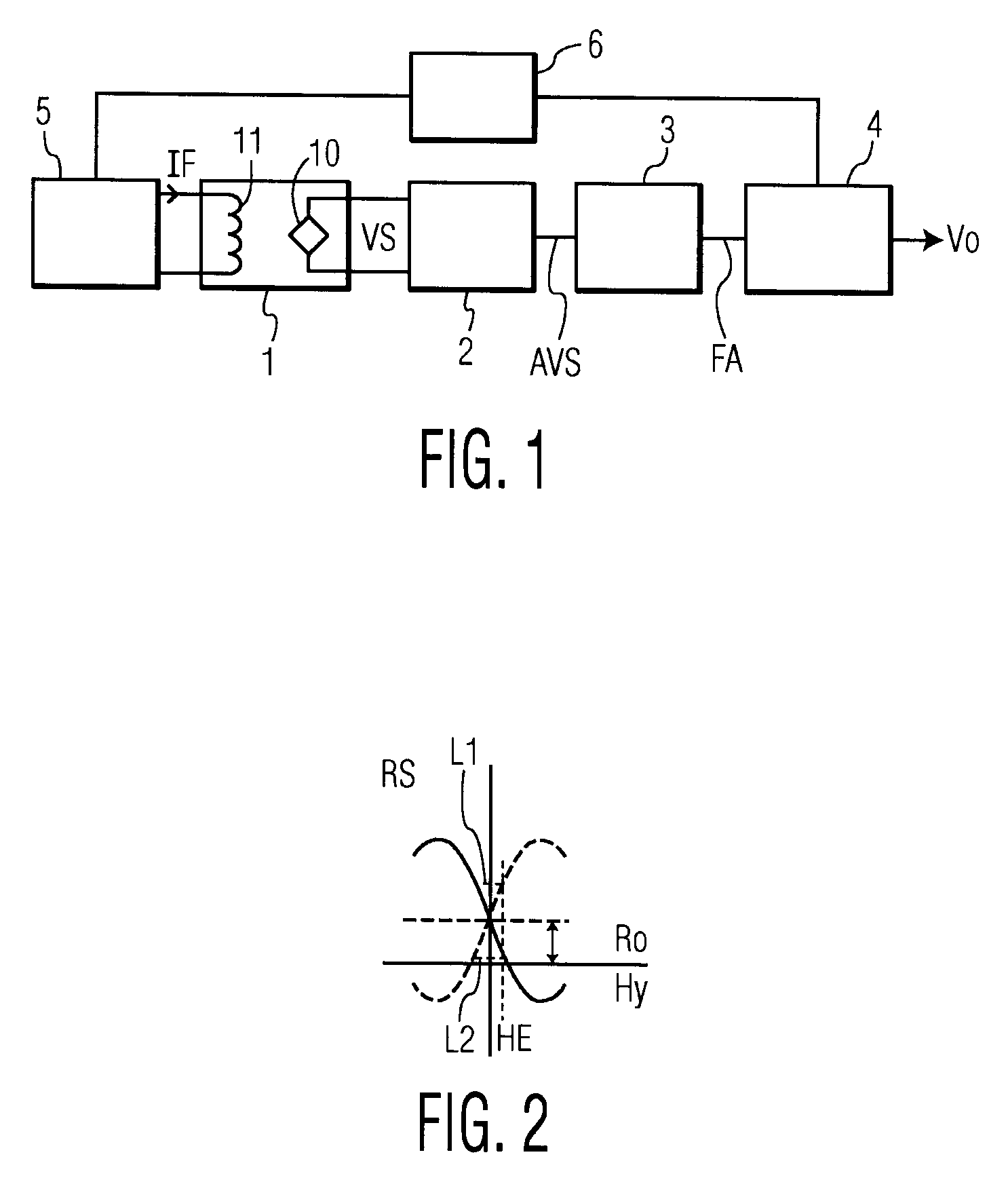
[0038]FIG. 1 shows a circuit diagram of a prior art magnetic field sensor circuit using a flipping coil. The magnetic field sensor circuit comprises a sense unit 1 comprising a magnetic field sensor 10 and a flipping coil 11, a pre-amplifier 2, an offset filter 3, a phase sensitive demodulator 4, a flipping driver 5, and a clock circuit 6.

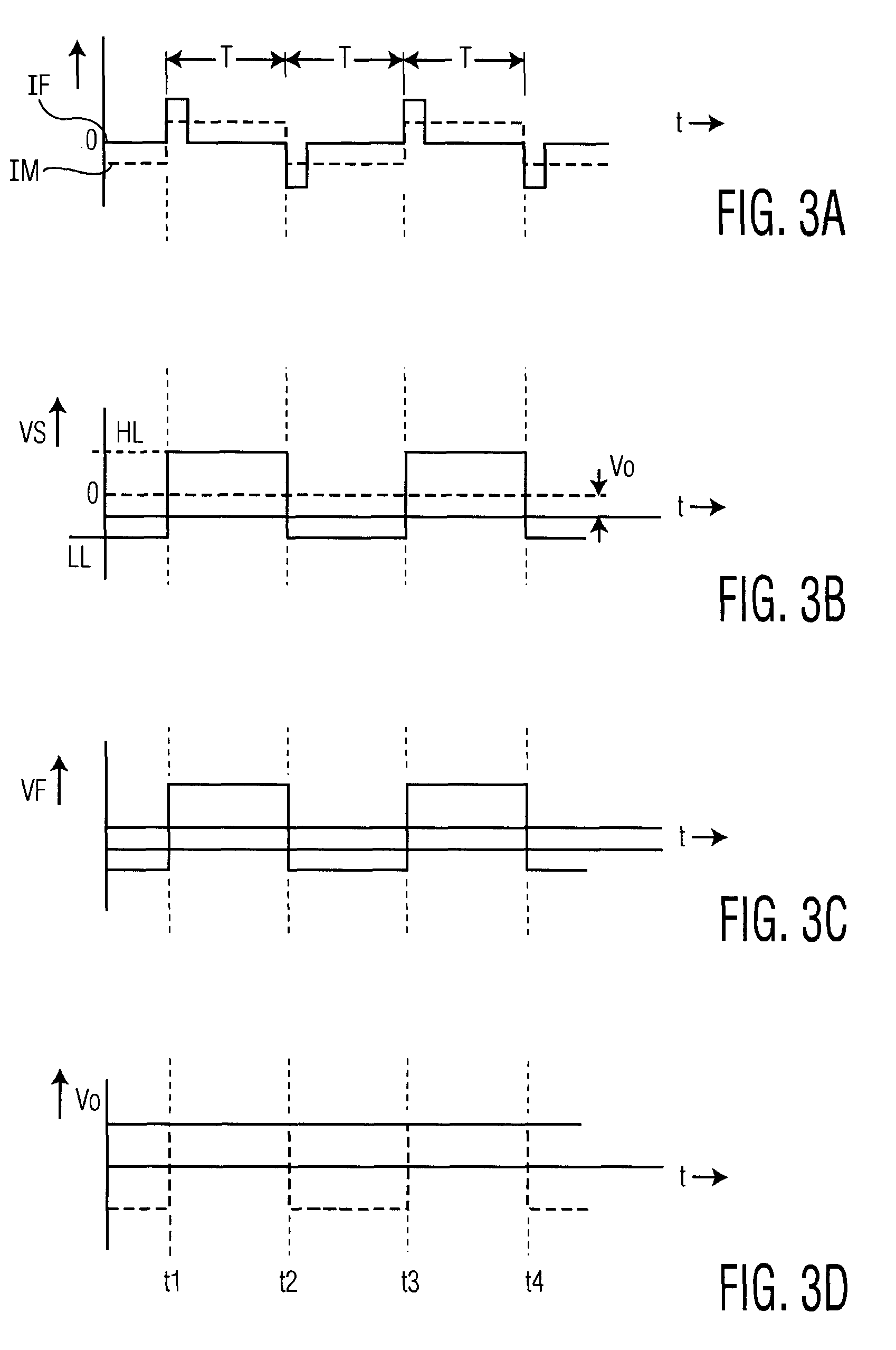
[0039]The flipping driver supplies a current IF through the flipping coil 11. The polarity of the current IF is periodically alternated to change the sensor operation between two stable operation modes in which the strip of sensor material is magnetized in opposite directions. Once the sensor 10 is put in one of the stable operation modes it will stay in this mode until the field applied is sufficiently strong the change the magnetization of the strip in the opposite direction. Thus, during a short time a current pulse IF is supplied to the flipping coil such that the strip is magnetized in one of the two directions. Next, this pulse is removed and...


PUM


Abstract

A magnetic field sensor circuit comprises a first magneto-resistive sensor (Rx) which senses a first magnetic field component in a first direction to supply a first sense signal (Vx). A first flipping coil (FC1) applies a first flipping magnetic field with a periodically changing polarity to the first magneto-resistive sensor (Rx) to cause the first sense signal (Vx) to have alternating different levels synchronized with the first flipping magnetic field. A second magneto -resistive sensor (Ry) senses a second magnetic field component in a second direction different than the first direction to supply a second sense signal (Vy). A second flipping coil (FC2) applies a second flipping magnetic field with a periodically changing polarity to the second magneto -resistive sensor (Ry) to cause the second sense signal (Vy) to have an alternating different levels synchronized with the second flipping magnetic field. The first flipping magnetic field and the second flipping magnetic field have a phase shift. A differential amplifier (AMP1) receives the first sense signal (Vx) and the second sense signal (Vy) to obtain a difference signal (Vd). A first synchronous demodulator (DEM1) receives the difference signal (Vd) and a first switching signal (Q1) being phase locked to the alternating different levels of the first sense signal (Vx) to supply a first output signal (Vox) indicating the first magnetic field component. A second synchronous demodulator (DEM2) receives the difference signal (Vd) and a second switching signal (Q2) being phase locked to the alternating different levels of the second sense signal (Vy) to supply a second output signal (Voy) indicating the second magnetic field component.

Description

FIELD OF THE INVENTION[0001]The invention relates to a magnetic field sensor circuit, an electronic compass comprising the magnetic field sensor circuit, a hand-held apparatus comprising the magnetic field sensor circuit, and a vehicle comprising the magnetic field sensor circuit.BACKGROUND OF THE INVENTION[0002]The Philips Semiconductors data sheet for discrete semiconductors with title “General Magnetic field sensors” of Jun. 12, 1998, further indicated by “File under Discrete Semiconductors, SC17” discloses a magnetic field sensor which comprises four magneto-resistive sensors arranged in a Wheatstone bridge.[0003]The magneto-resistive sensors are composed of a strip of ferromagnetic material called permalloy. The resistance of the magneto-resistive sensor depends on the angle between the current through the strip of ferromagnetic material and the internal magnetization vector. The internal magnetization vector depends on a strength of a component of an external magnetic field ap...

Claims


Application Information

Patent Timeline
Patent Type & Authority Patents(United States)
IPC IPC(8): G01C17/30
CPCB82Y25/00G01R33/093G01R33/096
Inventor DURIC, HARISIKKINK, TEUNIS JANBOEVE, HANS MARC BERT
Owner TITAN INTELLIGENCE TECH LTD
Why Eureka
Try Eureka