

Two step dry UO2 production process utilizing a positive sealing valve means between steps
a technology of positive sealing valve and uo2 powder, which is applied in the direction of uranium compounds, nuclear elements, greenhouse gas reduction, etc., can solve the problems of difficult operation, large amount of liquid waste, and inefficient or economical current procedures for converting ufsub>6/sub>to uosub>2, and achieve tight temperature control of each process step.
Active Publication Date: 2010-11-02
WESTINGHOUSE ELECTRIC CORP
View PDF37 Cites 12 Cited by
- Summary
- Abstract
- Description
- Claims
- Application Information
AI Technical Summary
Benefits of technology
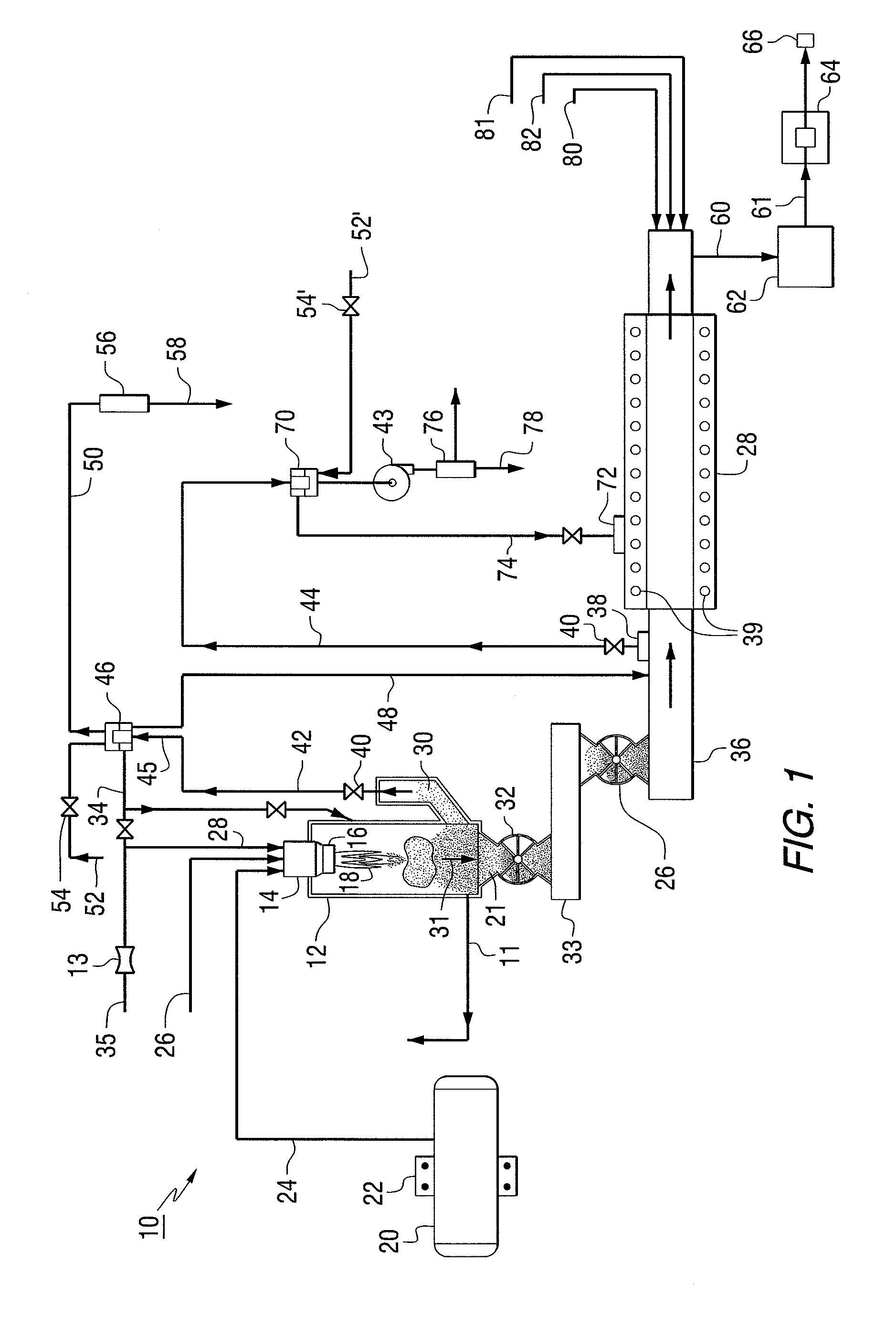
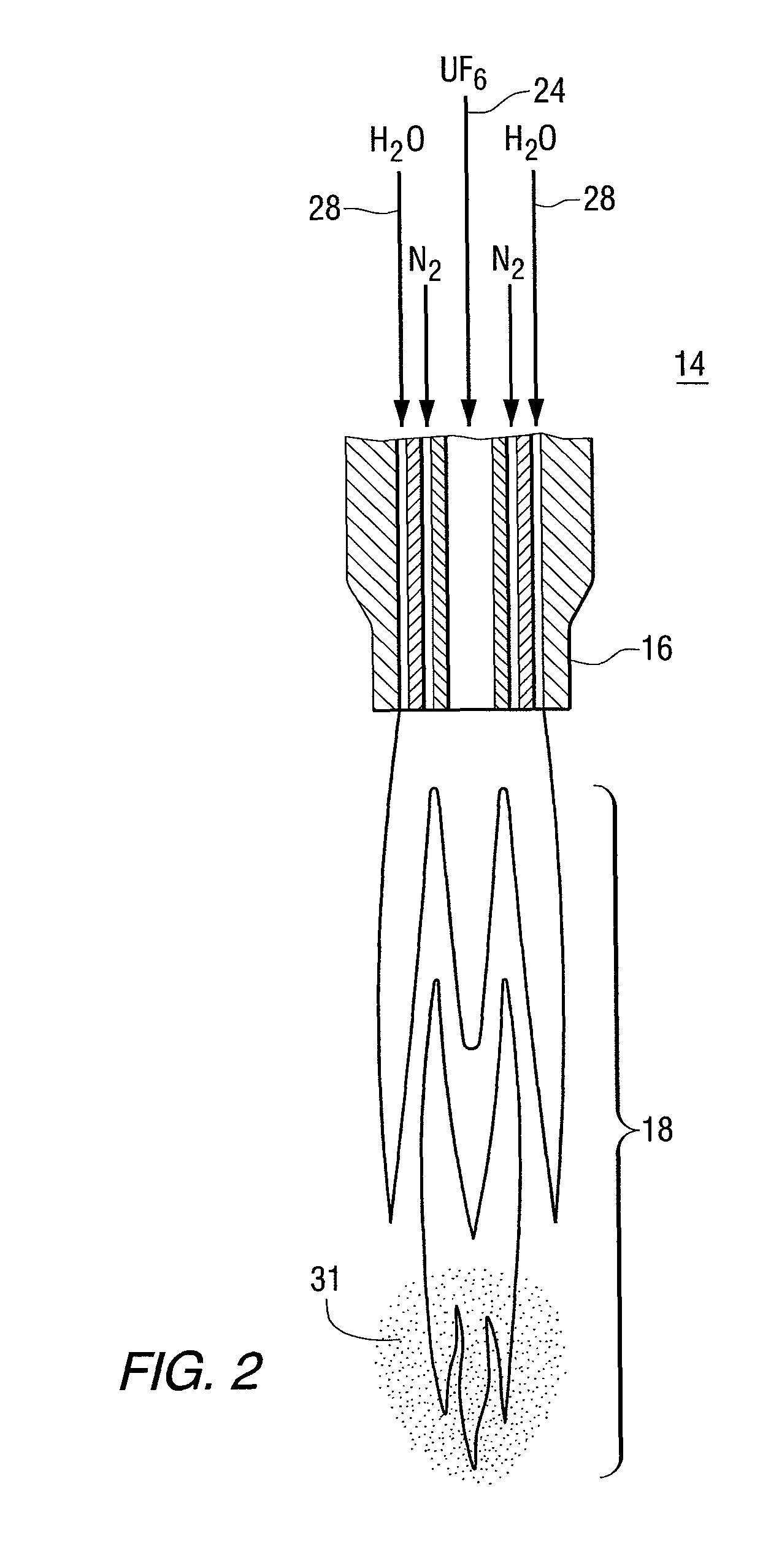
The present invention provides a multi-step process for producing high-quality nuclear grade, active uranium dioxide (UO2) powder. The process involves reacting uranium hexafluoride gas with steam and other gases in a flame reactor, followed by filtering and recycling of the initial product particles. The particles are then passed through a positive sealed valve and into a rotary kiln for further reduction and sintering. The process produces UO2 powder with a particle size range of 0.1-100 μm and a surface area range of 2-26 m2 / gm. The UO2 powder has a high density and is suitable for pressing into a pre-sintered pellet. The process also allows for control of the temperature and properties of the UO2F2 powder.
Problems solved by technology
While procedures for converting UF6 to uranium oxides are known, currently available procedures are not particularly efficient or economical for converting UF6 to UO2.
Furthermore, because of the need to control their ceramic properties and because of thermodynamic limitations, the known commercial conversion processes are either complex aqueous-based processes with multiple process stages or a one-stage dry process.
While the wet processes are easier to control, they produce large amounts of liquid wastes.
The single step dry process produces a minimal waste stream but is difficult to operate.
The UO2 product produced from this process tends to be very inactive and requires an intense milling step to produce moderately active powder.
In addition, there often is incomplete conversion of UO2F2 to UO3 / U3O8, which leads to unacceptable contamination in the final UO2 powder.
This likely is due to inadequate residence time and the growth of large particles in the initial phase which cannot complete the fluoride removal reaction.
The problem with these processes is the low feed rate due to the need to produce acceptable ceramic grade UO2 powder that can be made into dense UO2 pellets.
Handling therefore is delicate and rejects are numerous if special care is not exercised.
Part of the problem with this process is that two very exothermic processes occur in the same location at the tip of the mixing nozzle: (1) formation of UO2F2; and (2) some UO3 / U3O8 from the reaction of steam and entrained hydrogen from the surrounding atmosphere.
As the process flow rate is increased, the amount of hydrogen that is intermixed with the steam hydrolysis step becomes variable which produces large variations in the flame temperature and results in large variations in the powder properties.
The general problem with these processes is that step 1 production of UO2F2 is not, in fact, protected from H2 gas intrusion from step 2 formation of UO2 in a rotary kiln; and H2 intrusion into step 1 produces the variations in the powder properties described above.
with uncontrolled temperature which produces either unreactive or too reactive powder.
This method uses high value metal and therefore is not economically feasible.
In addition, this process produces a large amount of liquid waste that must be treated to remove the fluoride.
Disposal of these solids is difficult due to their origin in a nuclear facility.
The nitrate disrupts the ammonia recovery process due to the required addition of sodium hydroxide to free the ammonia from the nitrate.
Another problem is the carryover of NH4F in the dried UO3 / U3O8 product to the final calciner.
This process, however, is quite complicated, hard to operate and generates a UO2 product with much residual fluoride.
Notwithstanding the extensive prior efforts referred to above, there remains a substantial need for improved procedures for converting UF6 into solid UO2 that produces a highly active, ceramic grade UO2 powder at high production rates and which is easy to control, and which very importantly completely isolates steps where H2 reactant is completely excluded from initial first stage reactions, where it poses serious UO2 product variability problems.
Use of fluid bed processes are not an answer due to the issues with forming un-reactive, large solids and residual fluoride removal.
Method used
View moreImage
Smart ImageViewing Examples

Examples
example
[0064]In the first reaction, the steam / UF6 ratio of 0.2 by weight with the temperature in the flame reactor of 400° C.
[0065]In the rotary kiln reaction, the steam / H2 ration=20 by weight, with the temperature held at a maximum 600° C. The steam / UO2 ratio is about 0.8 by weight
[0066]The UO2 powder surface area is equal to approximately 4 meters2 / gm. The final density of pressed and sintered pellets was approximately 98.5%.
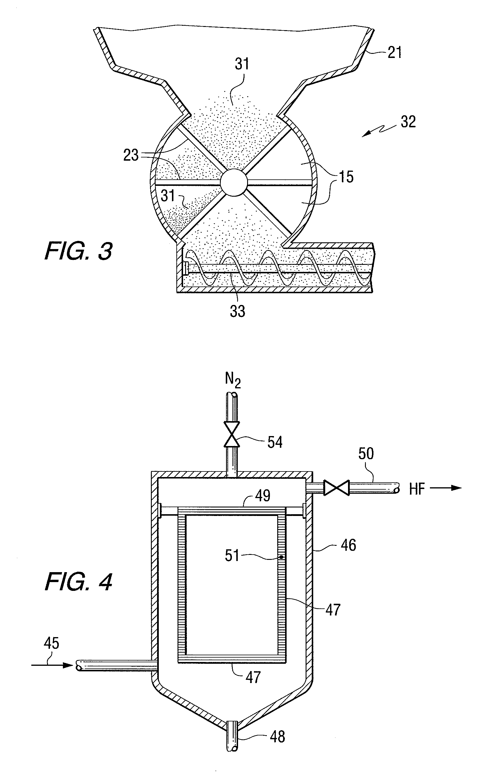
[0067]A positive valve seal—star valve is used between the first reaction and the rotary kiln.
Login to View More PUM
| Property | Measurement | Unit |
|---|---|---|
| temperature | aaaaa | aaaaa |
| temperature | aaaaa | aaaaa |
| temperature | aaaaa | aaaaa |
Abstract
The present invention provides a two-step process for producing nuclear grade, active uranium dioxide (UO2) powder in which the first step comprises reacting uranium hexafluoride (UF6) with steam in a flame reactor to yield uranyl fluoride (UO2F2); and the second step comprises removing fluoride and reducing UO2F2 to uranium dioxide (UO2) in a kiln under a steam / hydrogen atmosphere. The two-step process, each step separated by a positive sealed valve means to prevent gas, particularly H2 flow back, tightly controls the exothermicity of the reaction, which allows for a very tight temperature control which controls the growth of the particles and results in UO2 powder that is active and of consistent morphology.
Description
[0001]This present application is a Continuation-in-Part application that claims priority from U.S. Non-Provisional application Ser. No. 11 / 741,158, filed Apr. 27, 2007, now abandoned which U.S. Nonprovisional application claims priority to U.S. Provisional Application Ser. No. 60 / 833,232, filed Jul. 25, 2006, all of which is incorporated herein by reference.BACKGROUND OF THE INVENTION[0002]1. Field of the Invention[0003]The present invention relates to methods of manufacturing uranium oxide powder for use as nuclear fuel and, more particularly, to a two-step dry process for producing uranium oxide powder that eliminates the need for wet processing, and results in easy to handle UO2 powder and stable pellets.[0004]2. Description of the Prior Art[0005]The preparation of commercial nuclear fuels mainly has been by processes which use enriched and depleted uranium (i.e., enriched or depleted in the uranium-235 isotope compared to the uranium-235 content of naturally occurring uranium o...
Claims
Login to View More Application Information
Patent Timeline
 Patent Type & AuthorityPatents(United States)
IPC IPC(8): C01G43/00
CPCC01G43/00C01G43/025C01G43/06C01P2006/12C01P2006/80G21C3/623G21C19/48G21C21/00Y02E30/30Y02W30/50
InventorLAHODA, EDWARD J.
OwnerWESTINGHOUSE ELECTRIC CORP