Information recording method and apparatus using plasmonic transmission along line of ferromagnetic nano-particles with reproducing method using fade-in memory

a plasmonic transmission and information recording technology, applied in the field of magnetic recording medium, can solve the problems of imposing difficulty in increasing the recording density, reducing the resistance change, and reducing the detection density of information with further miniaturization

Inactive Publication Date: 2010-11-02
RICOH KK +1
View PDF5 Cites 7 Cited by
  • Summary
  • Abstract
  • Description
  • Claims
  • Application Information

AI Technical Summary

Benefits of technology

[0028]Thus, the present invention has a general object of solving the foregoing problems by improving the recording density and accessibility of information. More specifically, the present invention provides an information recording apparatus of increased recording density capable of reducing the problem of forming complex interconnections or heat generation caused by such complex interconnections and an information recording and reproducing method used therein.
[0031]According to the present invention, in which an oscillation mode of plasmon or near-field light is excited in a part of fine particles each including a ferroelectric metal and arrayed in a plane with a minute distance and in which the oscillation mode is caused to propagate along the fine particles, it becomes possible to read out the recorded information recorded in the array of the fine particles in the form of orientation of the magnetic moment of the fine particles, by detecting the change of the oscillation mode of the near-field light and the plasmon caused in the vicinity of the end part of the array of the fine particles. Thereby, it becomes possible to increase the recording density of the information while avoiding the problem of heat generation, or the like, caused when there are provided numerous complex interconnection patterns for improving the recording density and improving the accessibility of information.
[0045]According to the present invention, it becomes possible to increase the recording density of ultra large-capacity recording medium of petabyte class, while simultaneously solving the problem of difficulty of retrieving and accessing information at the time of performing recording and reproducing of information with such ultra large-capacity information receding medium.
[0061]Conventionally, there has been a need of displaying detailed information over the entire image with high resolution even in the case it is necessary to know only a part of the image in detail. Contrary to the foregoing, the fade-in memory of the present invention holds summary information for each block dividing the image region, and it is possible to provide the detailed display only for the regions where such detailed display is needed. As a result, high-speed display becomes possible.

Problems solved by technology

With such a construction, the degree of resistance change becomes small with device miniaturization, and it is expected that detection of information becomes difficult with further miniaturization.
Further, with increase of the recording density, it becomes necessary to provide a large number of complex interconnection patterns for accessing the information, while the problem of heat generation caused by the electric current flowing through the interconnection patterns or leakage current is no longer ignorable with increase in the integration density, and this also imposes difficulty for increasing the recording density.
Further, for realizing such ultra high-density memories of peta-byte class, mere increase of recording density is not sufficient, and reading and wiring of information becomes also an important problem.

Method used


Image

  • Information recording method and apparatus using plasmonic transmission along line of ferromagnetic nano-particles with reproducing method using fade-in memory
  • Information recording method and apparatus using plasmonic transmission along line of ferromagnetic nano-particles with reproducing method using fade-in memory
  • Information recording method and apparatus using plasmonic transmission along line of ferromagnetic nano-particles with reproducing method using fade-in memory

Examples


first embodiment

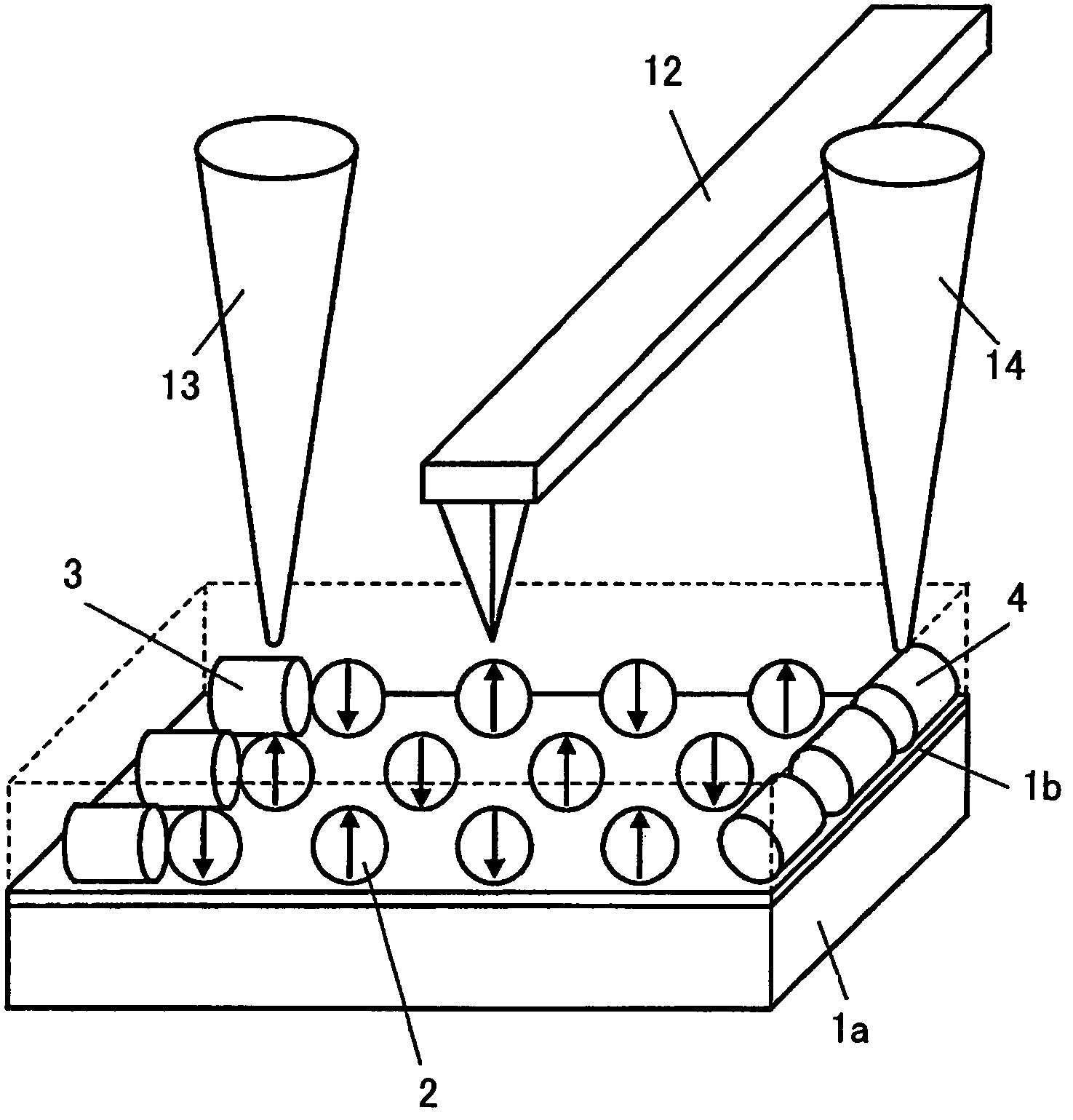
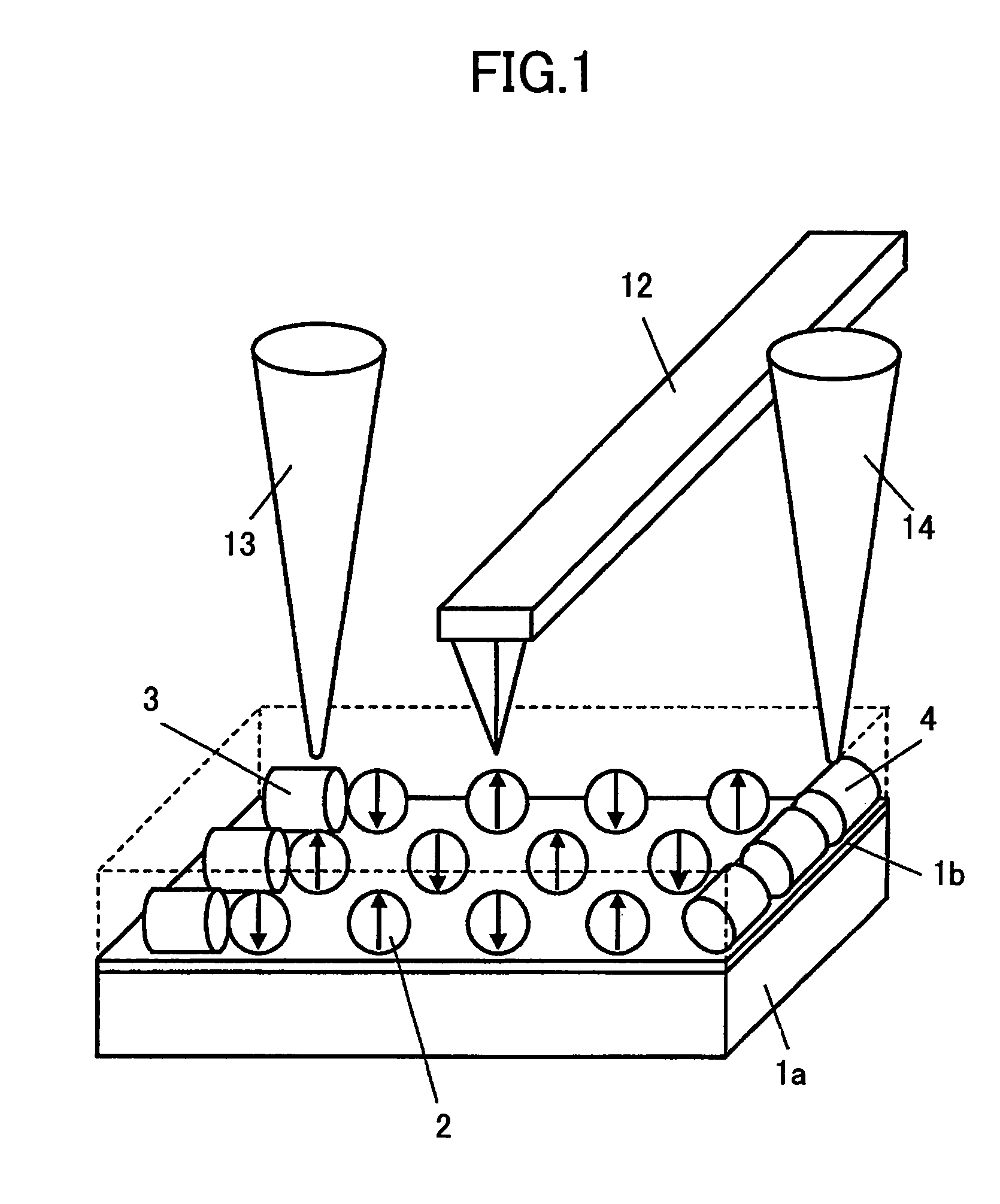
[0089]FIG. 1 is a diagram shows the schematic construction of an information recording apparatus according to a first embodiment of the present invention.

[0090]Referring to FIG. 1, there is formed an insulating thin film 1b on a conductive substrate 1a, and metal nanoparticles 2 are arrayed on a top surface thereof, wherein the metal nanoparticles 2 are fine particles each including therein a fine particle of ferromagnetic material. In the present embodiment, and also in the present invention, the word “ferromagnetic” further includes a ferrimagnetic material in addition to the ferromagnetic material of narrow definition. In FIG. 1, such fine particles are arrayed with a distance generally equal to the diameter of the metal nanoparticles 2 or with a distance not exceeding several times the diameter of the nanoparticles. The gap between the metal nanoparticles 2 may be left void or may be filled with a medium of small dielectric constant. Thus, the metal nano-particles 2 are electric...

second embodiment

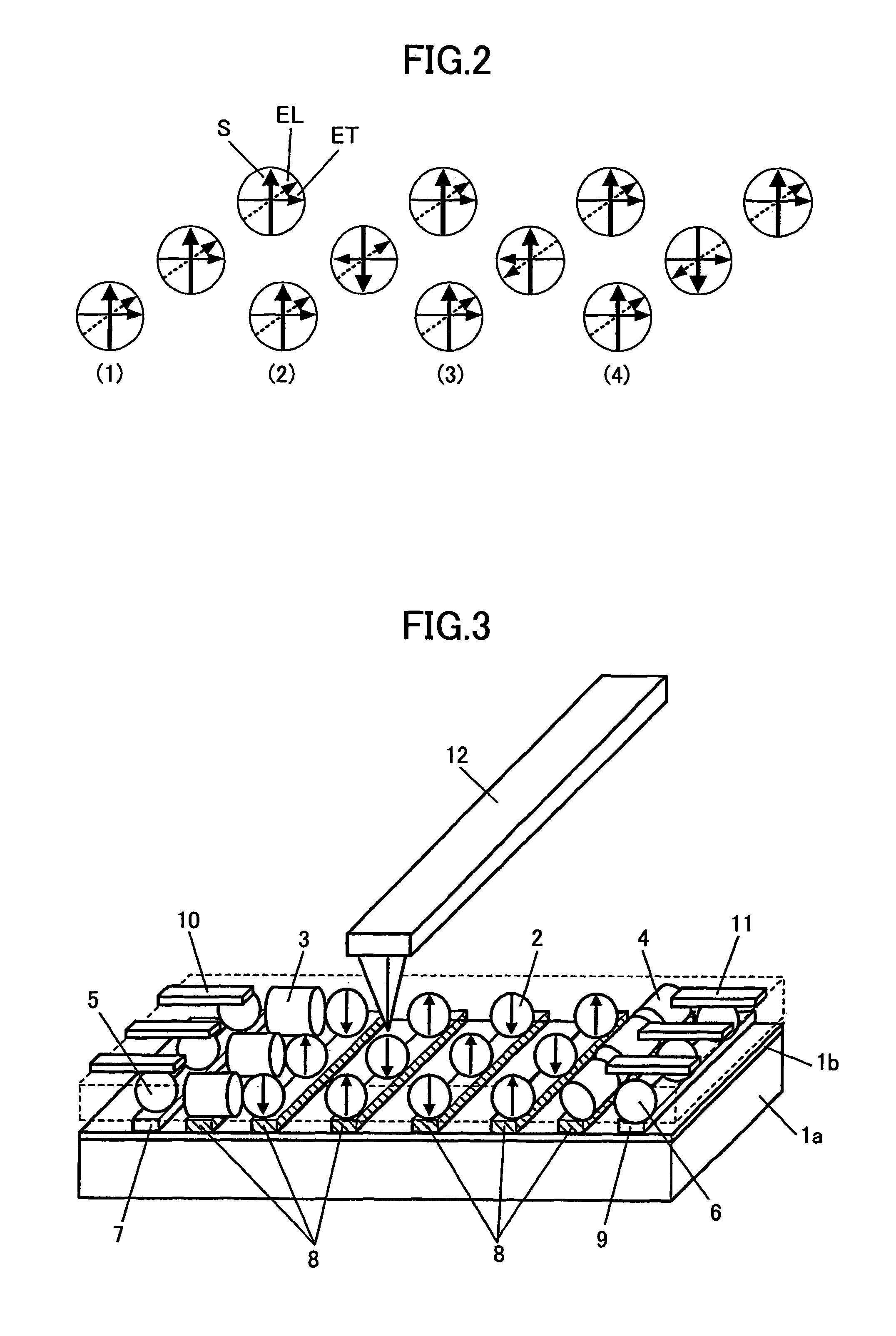
[0129]FIG. 3 is a diagram showing the schematic construction of an information recording apparatus according to a second embodiment of the present invention, wherein those parts corresponding to the parts described previously are designated by the same reference numerals and the description thereof will be omitted.

[0130]Referring to FIG. 3, the present embodiment has a construction generally identical to that of the first embodiment, except that there are disposed light-emitting devices 5 formed of semiconductor nanoparticles and photo-electric conversion elements 6 formed of semiconductor nanoparticles at respective ends of the metal nanoparticle array. Similarly to the previous embodiment, the gap between the metal nanoparticles 2 is filled with a material of low dielectric constant.

[0131]Further, with the construction of FIG. 3, there is provided an electrodes 7 on the insulating thin film 1b over the conductive substrate 1a in contact with the light-emitting devices 5, and there...

third embodiment

[0140]FIG. 4 is a diagram showing the schematic construction of an information recording apparatus according to a third embodiment of the present invention, wherein those parts corresponding to the parts described previously are designated by the same reference numerals and the description thereof will be omitted.

[0141]Referring to FIG. 4, the information recording apparatus of the present embodiment has a construction somewhat similar to that of the second embodiment, except that the present embodiment uses an insulating substrate 1 of an insulating material in place of the conductive substrate 1a. Further, with the present embodiment, it can be seen that the stripe shape electrode 7 is formed on the substrate 1 in contact with the light-emitting elements 5. Further, the stripe shape electrode 9 is formed in contact with the photo-electric conversion elements 6.

[0142]In the present embodiment, too, the gap between the metal nanoparticles 2 is filled with a material of low dielectri...


PUM

PropertyMeasurementUnit
atomic diameteraaaaaaaaaa
dielectric constantaaaaaaaaaa
sizeaaaaaaaaaa

Abstract

An information recording apparatus comprises a plurality of fine particles forming an array on a plane in close proximity of each other, each of the plural particles including a ferromagnetic metal, a light-emitting device for exciting a near-field light, and a photo-electric conversion element for detecting a near-field light traveled along the fine particles.

Description

BACKGROUND OF THE INVENTION[0001]The present invention relates to magnetic recording medium that uses near-field optics in combination with nano-structure fine particles that contain a ferromagnetic metal. Further, the present invention relates to an information recording apparatus capable of recording huge amount of information and a method for reproducing information from such an information recording apparatus of huge storage capacity.[0002]With increase in the amount of information handled in human society, recording density of recording media is increasing sharply in memory systems used for storing information. In the art of magnetic recording, recording capacity of the order of TB (terabytes) / inch2 is expected to be realized soon in the form of magnetic disks.[0003]The amount of information of the world has already reached the order of exabytes (1018 bytes), and processing of information of this amount is expected to become the matter of everyday life by the decade of the year...

Claims


Application Information

Patent Timeline
Patent Type & Authority Patents(United States)
IPC IPC(8): G11B21/02G01N21/55G01J3/44G02B6/10G11C8/00
CPCB82Y10/00G11B11/00G11C11/14G11B9/02G11C13/04
Inventor TAKAHASHI, MIGAKUTSUNODA, MASAKIYOSAITO, SHINOGAWA, TOMOYUKIFUJIMURA, ITARUMISAWA, SHIGEYOSHIKAWASAKI, TOSHIYUKI
Owner RICOH KK
Why Eureka
Try Eureka