Microcrystalline silicon thin film transistor

a thin film transistor and microcrystalline silicon technology, applied in the direction of coatings, chemical vapor deposition coatings, electric discharge tubes, etc., can solve the problems of limited frame refresh rate and pixel densities, and achieve the effect of stable device performance and high electron mobility

Inactive Publication Date: 2010-11-16
APPLIED MATERIALS INC
View PDF29 Cites 4 Cited by
  • Summary
  • Abstract
  • Description
  • Claims
  • Application Information

AI Technical Summary

Benefits of technology

[0009]Embodiments of the disclosure generally provide methods of forming microcrystalline thin film transistor devices providing high electron mobility and stable device performance. In one embodiment, a method for forming a microcrystalline silicon layer includes providing a substrate in a processing chamber, supplying a gas mixture having a hydrogen-based gas, a silicon-based gas and an argon gas into the processing chamber, the gas mixture having a volumetric flow ratio of the hydrogen-based gas to the silicon-based gas greater than about 100:1, wherein a volumetric flow ratio of the argon gas to the total combined flow of hydrogen-based gas and the silicon-based gas is between about 5 percent and about 40 percent, and maintaining a process pressure of the gas mixture within the processing chamber at greater than about 3 Torr while depositing a microcrystalline silicon layer on the substrate.

Problems solved by technology

The limited electron mobility inherent to conventionally processed amorphous silicon device results in limited frame refresh rates and pixel densities.

Method used


Image

  • Microcrystalline silicon thin film transistor
  • Microcrystalline silicon thin film transistor
  • Microcrystalline silicon thin film transistor

Examples


example 1

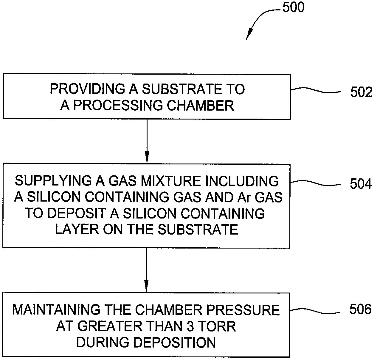
[0065]The table below shows the effects of using different H2 / SiH4 ratio (R) while depositing the microcrystalline silicon layer.

[0066]

IoffIonμSEaincubationμc-Si filmAAcm2 / VsecV / decIc / IaPh / DeVA200R6.6E−122.9E−070.071.241.981.00.09High400R1.6E−103.7E−070.064.023.542.50.20440600R3.1E−098.0E−070.086.353.6511.50.602901000R 8.7E−092.5E−060.255.703.6943.70.701602000R 7.6E−094.1E−060.375.165.1746.30.670

[0067]The first experimental data of 200R represents using a H2 / SiH4 ratio of about 200. Similarly, the second, third, fourth and fifth of the experimental data utilizes H2 / SiH4 ratio of about 400, 600, 1000 and 2000 respectively. As the R ratio increase, the crystalline fraction (Ic / Ia) value of the microcrystalline silicon layer increases. Furthermore, the thickness of the incubation layer is reduced as well with the increase of the R ratio. Additionally, Ea (activation energy) and the Ph / D (Photoconductivity / Dark conductivity) also increase with the increase of the R ratio, thereby indica...

example 2

[0068]Additionally, TEM (Transmission Electron Microscopy) data also indicates that with the increase of the ratio R of H2 / SiH4, the incubation layer formed at the substrate interface decreases. As discussed above, higher R ratio may assist depositing microcrystalline silicon layer with higher crystalline fraction. By utilizing the high ratio R of H2 / SiH4, the thickness of incubation layer, which is typically made from amorphous silicon at the beginning of the deposition process, may be efficiently reduced as amorphous silicon atoms are longer present in the beginning of the deposition process.

example 3

[0069]Additionally, the drain current versus gate voltage curve (Ids-Vg curve) measurement also indicates that with the increase of the ratio R, a higher On-current and Off-current may be obtained.


PUM

PropertyMeasurementUnit
pressureaaaaaaaaaa
pressureaaaaaaaaaa
pressureaaaaaaaaaa

Abstract

Methods for forming a microcrystalline silicon layer in a thin film transistor structure are provided. In one embodiment, a method for forming a microcrystalline silicon layer includes providing a substrate in a processing chamber, supplying a gas mixture having a hydrogen-based gas, a silicon-based gas and an argon gas into the processing chamber, the gas mixture having a volumetric flow ratio of the hydrogen-based gas to the silicon-based gas greater than about 100:1, wherein a volumetric flow ratio of the argon gas to the total combined flow of hydrogen-based gas and the silicon-based gas is between about 5 percent and about 40 percent, and maintaining a process pressure of the gas mixture within the processing chamber at greater than about 3 Torr while depositing a microcrystalline silicon layer on the substrate.

Description

CROSS-REFERENCE TO RELATED APPLICATIONS[0001]This application is a continuation-in-part of U.S. patent application Ser. No. 12 / 204,563, entitled “Microcrystalline Silicon Thin Film Transistor”, filed Sep. 4, 2008, which benefit of U.S. Provisional Application Ser. No. 61 / 027,809 filed Feb. 11, 2008 and U.S. Provisional Application Ser. No. 61 / 080,624, filed Jul. 14, 2008, all of which are incorporated by reference in their entireties.BACKGROUND OF THE INVENTION[0002]1. Field of the Invention[0003]Embodiments of the present invention generally relate to methods for forming a microcrystalline silicon film. More particularly, this invention relates to methods for forming a microcrystalline silicon film in thin film transistors devices.[0004]2. Description of the Related Art[0005]Plasma display panels and liquid crystal displays are frequently used for flat panel displays. Liquid crystal displays (LCD) generally contain two glass substrates joined together with a layer of a liquid cryst...

Claims


Application Information

Patent Timeline
Patent Type & Authority Patents(United States)
IPC IPC(8): H01L21/00
CPCC23C16/26H01J37/32009H01J37/32357H01J37/32862H01L21/02532H01L21/02595H01L21/0262H01L29/04H01L29/66742H01L29/7866
Inventor WON, TAE KYUNGCHOI, SOO YOUNGYIM, DONG KILCHEN, JRIYAN JERRYPARK, BEOM SOO
Owner APPLIED MATERIALS INC
Why Eureka
Try Eureka