Voltage-controlled oscillator and communication device using the same

a technology of voltage control and communication device, applied in pulse generators, pulse techniques, electrial characteristics varying frequency control, etc., can solve problems such as adding more difficulties in design

Active Publication Date: 2010-11-23
HITACHI LTD
View PDF24 Cites 31 Cited by
  • Summary
  • Abstract
  • Description
  • Claims
  • Application Information

AI Technical Summary

Benefits of technology

[0008]That is to say, it is important that an oscillator for use in millimeter-wave band radio communications must provide an LO signal with large signal power to the mixer circuit having a predetermined input impedance. To do so, the oscillator first matches an output impedance to a predetermined level and then provides a large power signal. Impedance matching needs to be done regardless of whether an oscillator or a mixer circuit is configured in a separate chip to form a radio communication module performing inter-chips transmission, or whether the oscillator and the mixer circuit are integrated on one semiconductor substrate. In particular, the impedance is crucial for high-frequency oscillators. Needless to say, such performance should be achieved at low power consumption.
[0011]Since an alternating current of an oscillation frequency that is determined by the resonant frequency of a resonator 10 flows from the collector nodes of the Q1 and Q2 to the impedance-matching circuit 40, the impedance-matching circuit 40 converts the current into a voltage. That is, in order for the impedance-matching circuit 40 to convert / output a current signal of the oscillation frequency determined at the resonator 10 into a voltage signal, resonator parameters may be designed without taking account of impedance matching, thereby optimizing performance in the oscillator.
[0012]However, in the case of the oscillator shown in FIG. 29, phases of a collector signal and a base signal are different in 180 degree each other. If an output signal of the collector is enlarged, collector base capacitance between the base node and the collector node (CBC) looks larger because of the mirror effect. It causes the problem of narrowing the variable frequency range due to reduction of the turnable-capacitance ratio to the total capacitance of the oscillation circuit. Therefore, as in the oscillator proposed by the above “SiGe BiCMOS 65-GHz BPSK Transmitter and 30 to 122 GHz LC-Varactor VCOs with up to 21% Tuning Range”, a cascode amplifier is additionally connected to the collectors of Q1 and of Q2 in FIG. 29 and an impedance-matching circuit is provided to the collector of the cascode amplifier, so that an output may be taken out from the collector of the cascode amplifier. With the use of the cascode amplifier, collector signals of the Q1 and Q2 have significantly reduced amplitude ranges. This enables to avoid an increase in capacitor between base and collector due to the mirror effect. Nevertheless, even this method has a drawback of high power consumption because an extra supply voltage is needed to make use of the cascode amplifier.
[0014]As mentioned earlier, Japanese Patent Application Laid-Open Publication No. H03-29504 discloses an oscillator introducing a transformer for output, which has adopted a conventional scheme for matching an output impedance through the impedance conversion. However, since the oscillator of Japanese Patent Application Laid-Open Publication No. 3-29504 uses an inductor of the resonator as a transformer, it is easily susceptive to the influence of noises from a load circuit connected to a secondary inductor of the transformer.
[0022]It is, therefore, an object of the present invention to provide a voltage-controlled oscillator capable of outputting a large power signal by matching an output impedance to a predetermined level at low power consumption, and a communication device using the same.
[0024]According to the present invention, it becomes possible to realize a voltage-controlled oscillator capable of outputting a large power signal by matching an output impedance to a predetermined level at low power consumption, and a communication device incorporating the same.

Problems solved by technology

However, these requirements add more difficulties in designing.

Method used


Image

  • Voltage-controlled oscillator and communication device using the same
  • Voltage-controlled oscillator and communication device using the same
  • Voltage-controlled oscillator and communication device using the same

Examples


embodiment 1

[0060]A first embodiment of the present invention is explained with reference to FIGS. 1 through 3.

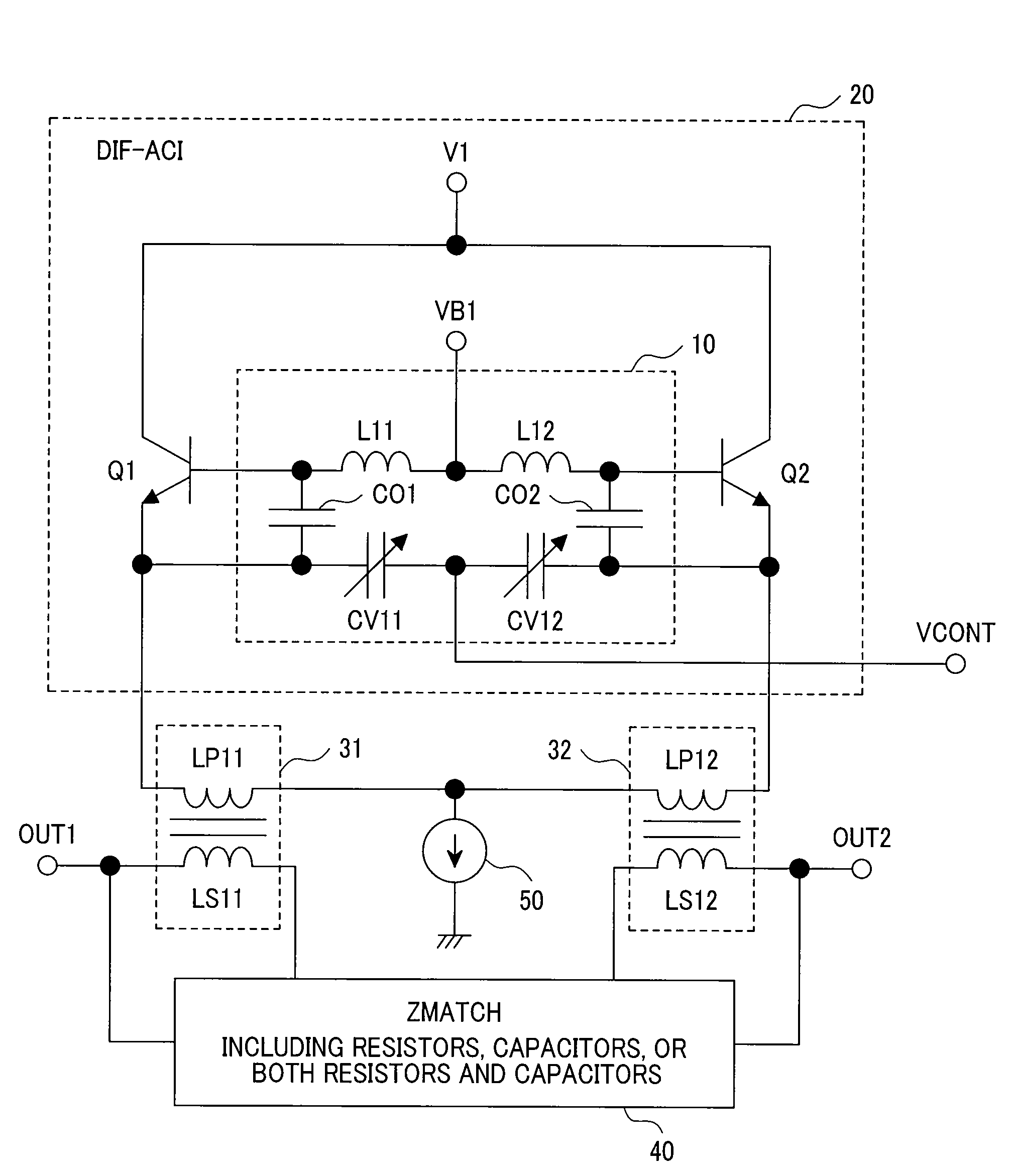
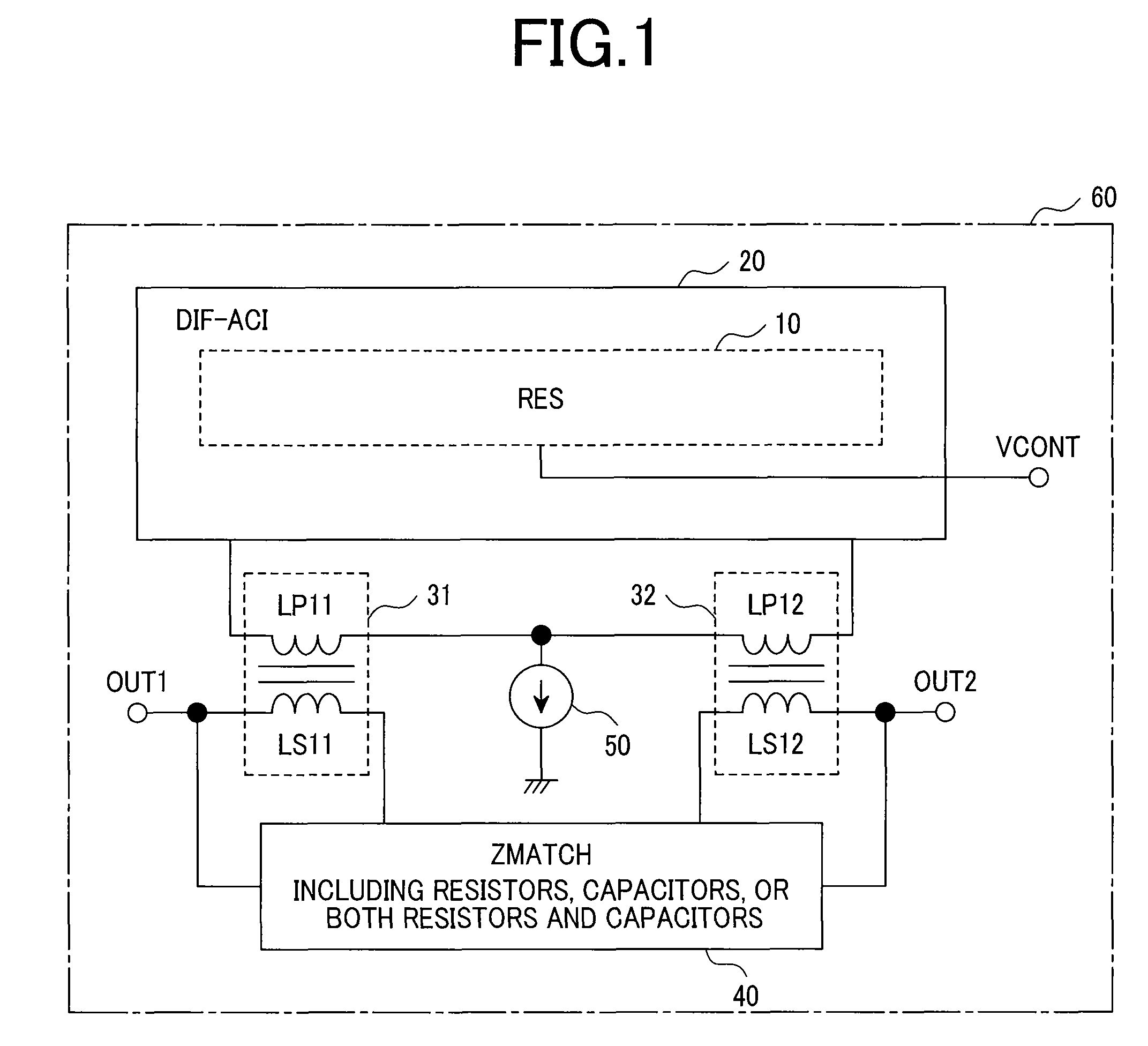
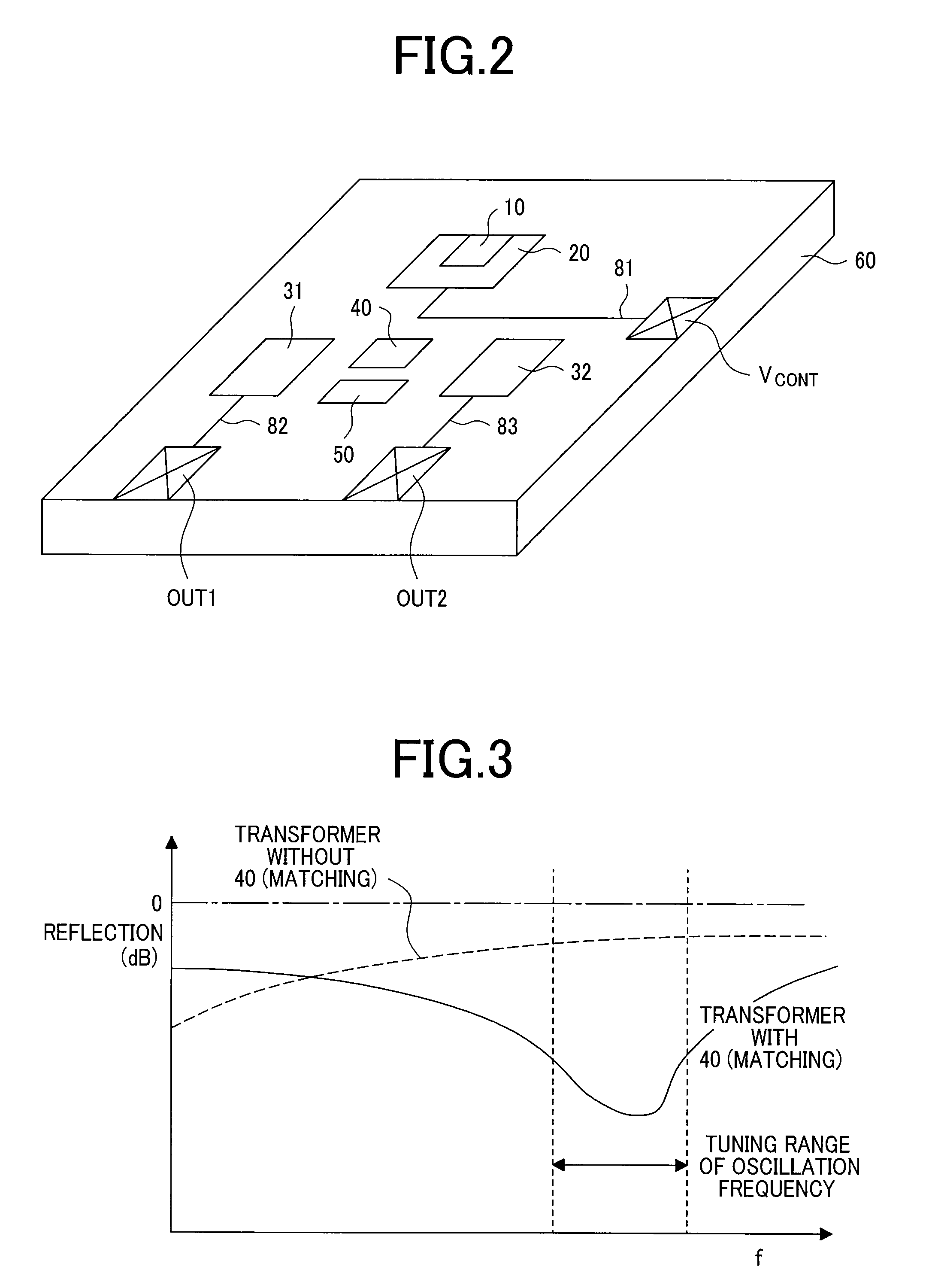
[0061]FIG. 1 is a schematic circuit diagram of a voltage-controlled oscillator according to a first embodiment of the present invention. FIG. 2 is a perspective view, showing that the voltage-controlled oscillator of the first embodiment is fabricated on a substrate. FIG. 3 diagrammatically shows reflection characteristics of the voltage-controlled oscillator of the first embodiment.

[0062]As can be seen in FIG. 1 and FIG. 2, a voltage-controlled oscillator of the present invention comprises a differential alternating current generator 20 including a resonator 10, for generating two-phase (a pair of differential) alternating current having the same frequency with the resonant frequency of the resonator 10 yet being 180 degrees out of phase in mutual; a pair of transformers 31 and 32, each having a primary inductor LP11, LP12 connected to the differential alternating current generator 20...

embodiment 2

[0068]A second embodiment of the present invention is explained with reference to FIG. 4. A voltage-controlled oscillator of this embodiment comprises a differential alternating current generator 20 including a resonator 10, for generating two-phase (a pair of differential) alternating current having the same frequency with the resonant frequency of the resonator 10 yet being 180 degrees out of phase in mutual; and transformers 31 and 32, each having a primary inductor LP11, LP12 connected to the differential alternating current generator 20 and a secondary inductor LS11, LS12 connected to an impedance-matching circuit 40. The impedance-matching circuit 40 is connected serially to the secondary inductors of the transformers 31 and 32. The oscillation frequency of the voltage-controlled oscillator is determined by the resonant frequency of the resonator 10. The resonator 10 includes a frequency control terminal group VCONT composing at least one frequency control terminal capable of ...

embodiment 3

[0077]A third embodiment of the present invention is explained with reference to FIG. 5. A voltage-controlled oscillator of this embodiment comprises a differential alternating current generator 20 including a resonator 10, for generating two-phase alternating current having the same frequency with the resonant frequency of the resonator 10 yet being 180 degrees out of phase; and a pair of transformers 31 and 32, each having a primary inductor connected to the differential alternating current generator 20 and a secondary inductor connected to an impedance-matching circuit 40. The impedance-matching circuit 40 is connected serially to the secondary inductors of the transformers 31 and 32.

[0078]With the configuration shown in FIG. 5, signal power of the oscillation frequency being accumulated at the resonator is outputted after matching an output impedance to a predetermined impedance, so the voltage-controlled oscillator of this embodiment consumes less power and is capable of effici...


PUM


Abstract

The present invention provides a voltage-controlled oscillator operating from microwave frequencies to millimeter wave frequencies, which is capable of outputting a large power with an output impedance thereof being set up to a predetermined level at low power consumption, and a communication device using the same. The voltage-controlled oscillator includes: a differential alternating current generator including a resonator capable of varying resonant frequency according to an input control voltage, for generating a pair of differential alternating current each of which having the same frequency with the resonant frequency of the resonator yet being 180 degrees out of phase in mutual; a pair of transformers each of which having a primary inductor and a secondary inductor, for conducting the alternating current to the primary inductor; and an impedance-matching circuit connected to the secondary inductor of the transformers, wherein an output signal is outputted from the secondary inductors of the transformers.

Description

CLAIM OF PRIORITY[0001]The present invention claims priority from Japanese Patent Application JP 2007-10092 filed on Jan. 19, 2007, the content of which is hereby incorporated by reference onto the application.FIELD OF THE INVENTION[0002]The present invention relates to a voltage-controlled oscillator capable of setting an output impedance thereof to a predetermined value, and a communication device using the same.BACKGROUND OF THE INVENTION[0003]Hao Li, and Hans-Martin Rein, “Millimeter-Wave VCOs With Wide Tuning Range and Low Phase Noise, Fully Integrated in a SiGe Bipolar Production Technology,” IEEE JOURNAL OF SOLID-STATE CIRCUITS, VOL. 38(2), pp. 184-191, 2003 discloses an oscillator whose output comes from a load-connected collector in a differential Colpitts oscillator effective for low phase noise performance. C. Lee, T. Yao, A. Mangan, K. Yau, M. A. Copeland and S. P. Voinigescu, “SiGe BICMOS 65-GHz BPSK Transmitter and 30 to 122 GHz LC-Varactor VCOs with up to 21% Tuning R...

Claims


Application Information

Patent Timeline
Patent Type & Authority Patents(United States)
IPC IPC(8): H03B5/08H03B5/18H03B5/02H03B5/12H04B1/40
CPCH03B5/1228H03B5/1231H03B5/1209H03B5/124H03B2201/0208
Inventor NAKAMURA, TAKAHIROMASUDA, TORU
Owner HITACHI LTD
Why Eureka
Try Eureka