
Steam-hydrocarbon reforming method with limited steam export

a technology of steam hydrocarbon and export, which is applied in the direction of machines/engines, mechanical equipment, energy input, etc., can solve the problems of increased capital expenditure, increased cost, and inability to meet the needs of steam export, so as to maintain the overall plant efficiency and lessen the impact of plant efficiency

Inactive Publication Date: 2010-12-14
AIR PROD & CHEM INC
View PDF22 Cites 20 Cited by
  • Summary
  • Abstract
  • Description
  • Claims
  • Application Information

AI Technical Summary

Benefits of technology

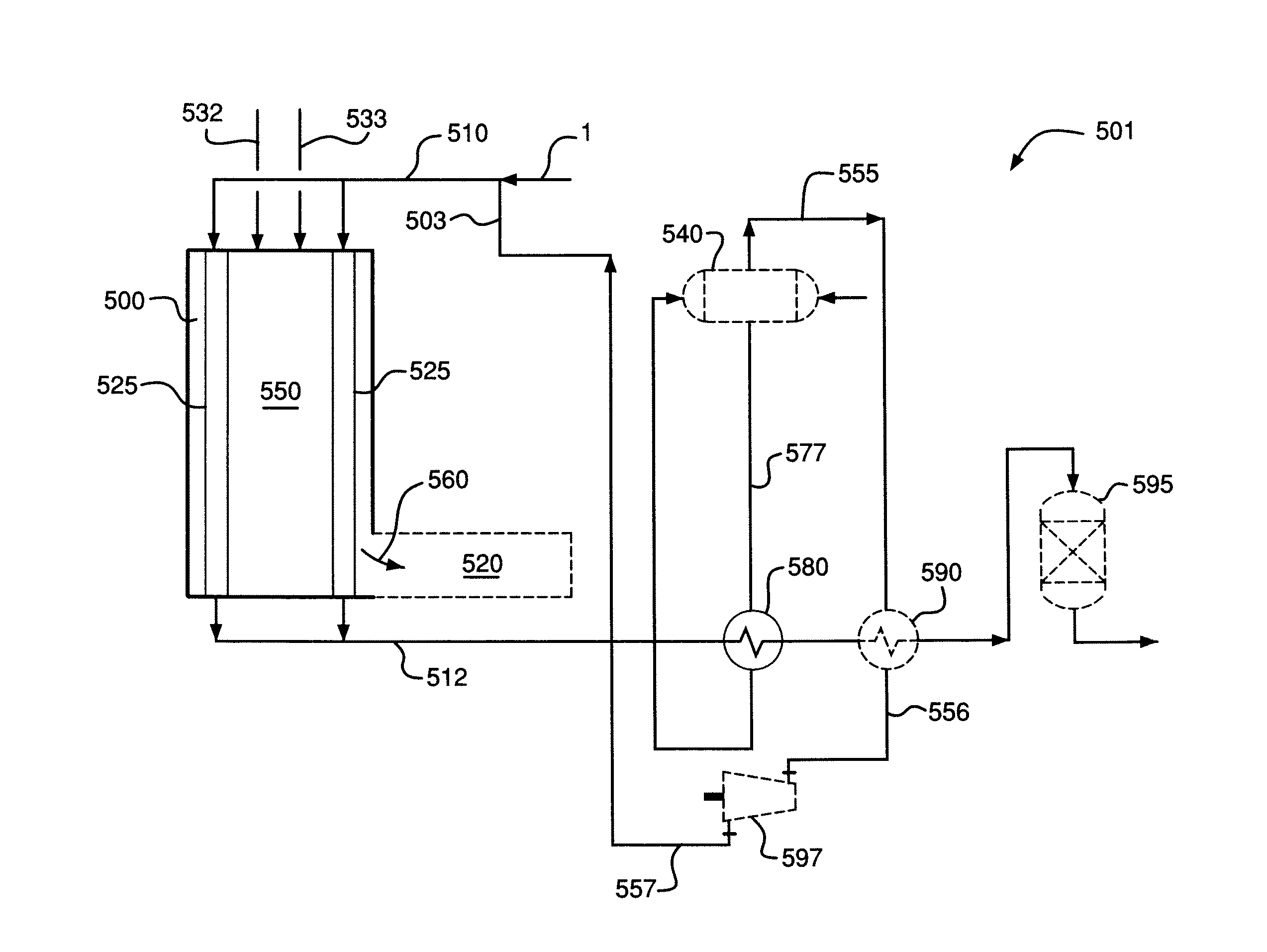
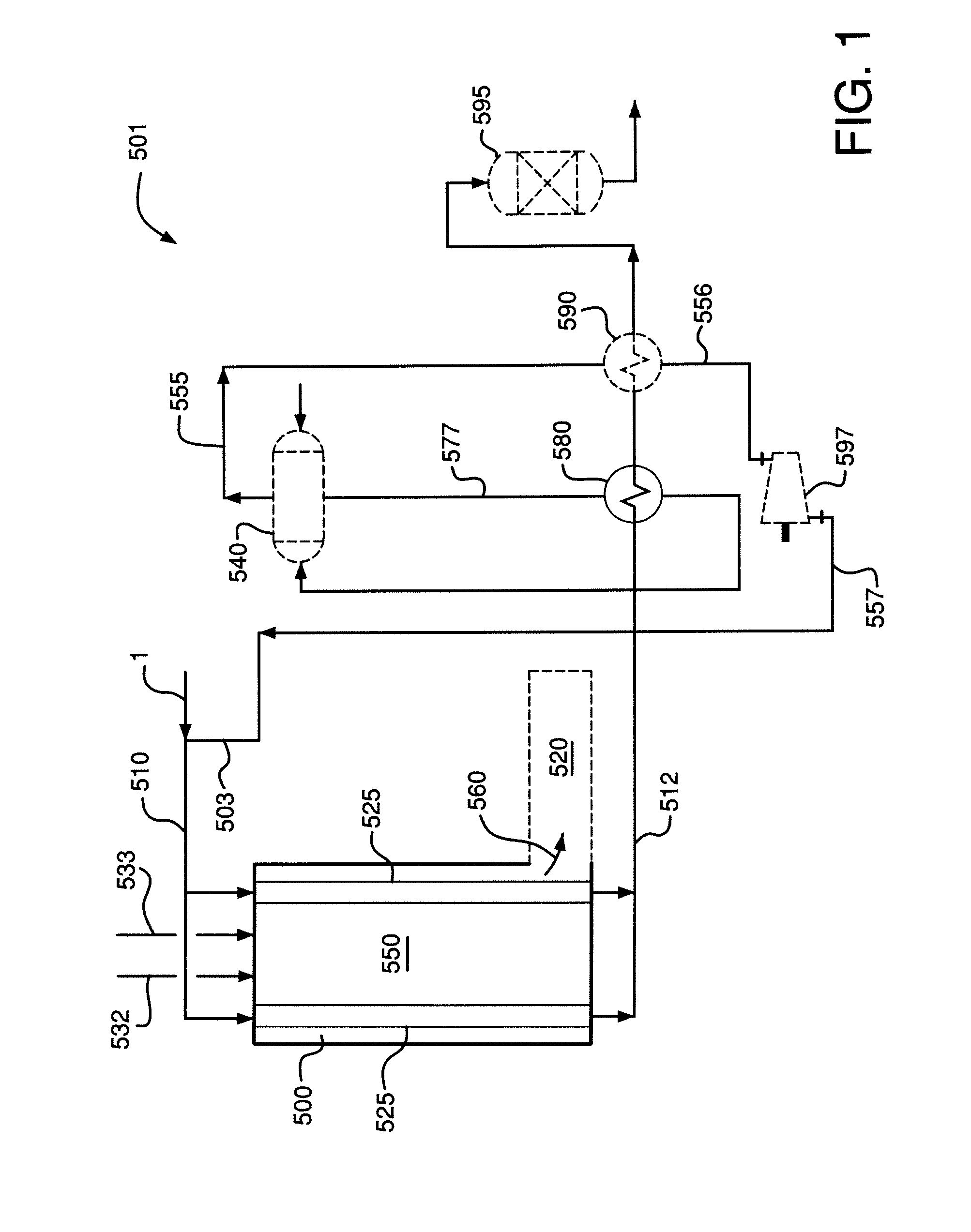
The present invention relates to a method for generating hydrogen in a production facility. The method involves using a reformer to convert hydrocarbon into hydrogen and carbon dioxide through a reaction with steam. The method includes introducing a fuel, oxygen, and nitrogen into a combustion section of the reformer, where they react to produce heat and a fuel-containing gas mixture. The gas mixture is then introduced into a plurality of catalyst-containing tubes in a catalytic steam reformer, where it reacts with the steam to form hydrogen. The hydrogen is then used to generate power through a steam turbine. The method can also include using the power generated by the steam turbine for oxygen generation. The technical effects of the invention include improved efficiency and reduced emissions in the production of hydrogen.

Problems solved by technology

However, exporting steam requires expensive pipeline systems including control and safety valves, steam traps, heat tracing, etc.
Both options require additional capital expenditure and can be cost prohibitive for projects where there is no customer willing to buy the steam at a reasonable cost, or power can not be produced competitively.
For small hydrogen production units where steam export is not justified, a portion of the excess steam is often used in the process less efficiently or vented.
The hydrogen plant may be designed with less heat recovery equipment resulting in a less efficient plant.
However, the use of air preheat and / or a performer still has significant waste heat and can not provide suitable efficiencies without taking credit for steam export.
When credit for the steam produced can not be reasonably factored in to the efficiency of the synthesis gas generating facility, methods are required to lessen the impact on plant efficiency.

Method used


Image

  • Steam-hydrocarbon reforming method with limited steam export
  • Steam-hydrocarbon reforming method with limited steam export
  • Steam-hydrocarbon reforming method with limited steam export

Examples


example 1

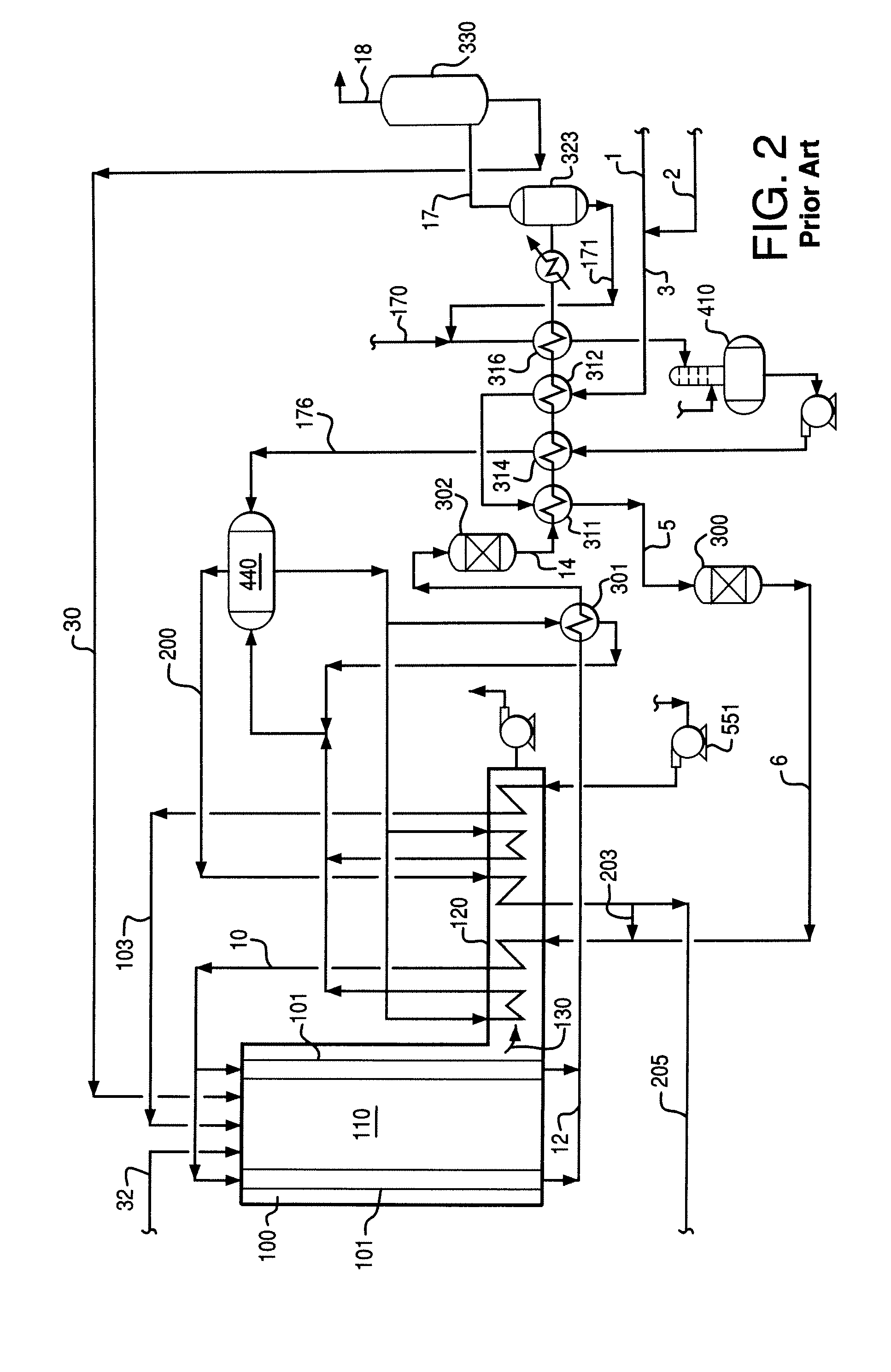
[0099]The configuration according to Example 1 is shown in FIG. 2. FIG. 2 is a process flow diagram for a prior art-type hydrogen production facility. A reformer feedstock 1, in this example, natural gas is mixed with a hydrogen recycle stream 2 to form a hydrogen-containing feed stream 3. The hydrogen-containing feed stream 3 is heated via indirect heat exchange with a shift reactor effluent stream 14 from shift reactor 302 in heat exchangers 311 and 312. The shift reactor effluent stream 14 is formed from a reformed gas mixture 12 from the reformer 100 by reaction in shift reactor 302.

[0100]The heated hydrogen-containing feed stream 5 is introduced into hydrodesulphurization unit 300 to remove sulfur and form a sulfur-depleted reformer feedstock 6. Sulfur in the reformer feedstock is removed to prevent poisoning of reforming catalyst.

[0101]Reformer feed gas mixture stream 10 is formed from feed steam stream 203 and sulfur-depleted reformer feedstock 6 by mixing followed by indirec...

example 2

[0116]The configuration according to Example 2 is shown in FIG. 3. FIG. 3 is a process flow diagram for a prior art-type hydrogen production facility that includes a performer. With the exception of the adiabatic performer 105 and some heat exchangers, the configuration according to Example 2 is the same as the configuration according to Example 1 in FIG. 2. Where there are like elements in FIG. 2 and FIG. 3, like reference numbers are used.

[0117]A difference is that reformer feed gas mixture stream 10 is formed from feed steam stream 203 and sulfur-depleted reformer feedstock 6 by mixing followed by indirect heat exchange with combustion product gases in the convection section 120 of the reformer 100, prereforming in performer 105 and heating again in the convection section 120. Otherwise, the description of the configuration provided for Example 1 applies mutatis mutandis to the configuration of Example 2.

[0118]The process according to Example 2 was modeled using commercial proces...

example 3

[0122]The configuration according to Example 3 is shown in FIG. 4. FIG. 4 is a process flow diagram for a prior art-type hydrogen production facility that includes a performer. In this configuration a medium temperature shift reactor303 is used in place of a high temperature shift reactor. Some of the heat recovery has been modified accordingly. Otherwise, the configuration of Example 3 is very similar to the configuration of Example 2. Where there are like elements in FIGS. 2, 3 and 4, like reference numbers are used.

[0123]The description of the configuration provided for Examples 1 and 2 apply mutatis mutandis to the configuration of Example 3. Differences will be apparent to one skilled in the art based on the process flow diagram.

[0124]The process according to Example 3 was modeled using commercial process simulator software.

[0125]Input parameters and results for this configuration are summarized in Table 1.

[0126]As shown in Table 1, according to the simulation results, about 64...


PUM

PropertyMeasurementUnit
molar ratioaaaaaaaaaa
pressureaaaaaaaaaa
pressureaaaaaaaaaa

Abstract

A method for generating hydrogen and / or synthesis gas in a production facility where little or no export steam is produced. Most or all of the high pressure steam produced from the waste heat from the process is used in the steam-hydrocarbon reformer with little or no steam export. The method uses oxygen enhanced combustion which may involve oxygen lancing and / or oxygen-enrichment. Plant efficiencies using the method and prior art-type methods are compared.

Description

CROSS-REFERENCE TO RELATED APPLICATIONS[0001]This patent application claims priority to provisional application U.S. Ser. No. 61 / 037,190 filed on Mar. 17, 2008, the contents of which are hereby incorporated by reference.BACKGROUND[0002]The present invention relates to a method for generating hydrogen and / or synthesis gas by steam-hydrocarbon reforming along with generating steam using waste heat from the steam-hydrocarbon reforming process. More particularly, the present invention relates to such a process using oxygen-enhanced combustion in the reformer with little or no steam export.[0003]Synthesis gas is used to produce products such as ammonia, methanol and hydrogen. Synthesis gas is generated by high temperature processes where a lot of waste heat is available. The waste heat is generally used to generate steam and helps to improve the overall efficiency of the synthesis gas facility. In typical facilities, the amount of steam generated from the waste heat significantly exceeds...

Claims


Application Information

Patent Timeline
Patent Type & Authority Patents(United States)
IPC IPC(8): C01B3/24C01B3/26
CPCC01B3/384C01B3/48C01B2203/84C01B2203/0233C01B2203/0283C01B2203/0288C01B2203/0294C01B2203/043C01B2203/047C01B2203/048C01B2203/0495C01B2203/06C01B2203/0816C01B2203/0827C01B2203/0883C01B2203/0894C01B2203/1058C01B2203/142C01B2203/146C01B2203/148Y02P20/129
Inventor GENKIN, EUGENE S.DIMARTINO, SR., STEPHEN PAULALVAREZ, MIGUEL RAFAELZAGNOLI, DAVID ANTHONYHARRIS, CHRISTOPHER FRANCIS
Owner AIR PROD & CHEM INC
Learn More