Control device and control method of boost converter

a control device and converter technology, applied in the direction of process and machine control, motor/generator/converter stopper control, electric generator control, etc., can solve the problems of difficult to perform a series of control processes at a high speed, difficult to reduce the processing load occurring upon performing a series of control processes, etc., to achieve the effect of expanding the running area

Active Publication Date: 2010-12-14
HONDA MOTOR CO LTD
View PDF24 Cites 25 Cited by
  • Summary
  • Abstract
  • Description
  • Claims
  • Application Information

AI Technical Summary

Benefits of technology

[0008]In the control device of the boost converter having the above-described configuration, since the boost voltage command is set on the basis of the counter electromotive voltage of the brushless DC motor and the toque command for the brushless DC motor, a boost control process can be performed at independent timing with a current supply control process for the brushless DC motor. Accordingly, it is possible to reduce processing load when performing these control processes, and perform the control processes at a high speed without mutual interference in the control processes.
[0021]In the control method of the boost converter having the above-described configuration, it is possible to expand the running area from the running area attainable by the boost control process to the higher speed rotation side, by supplying the weak field current during the boost control process when the input voltage of the inverter circuit varying with the increase in the rotation number of the brushless DC motor, that is, the increase in the counter electromotive voltage becomes higher than the boost voltage.

Problems solved by technology

However, in the known control device, since a boost control process which sets a boost voltage command and a current supply control process for the electric motor (that is, the current feedback control process or the calculation process based on the voltage equation) are not performed at independent timing one another, it is difficult to reduce processing load occurring upon performing a series of control processes.
Moreover, it is difficult to perform the series of control processes at a high speed, because these processes are interfered one another.

Method used


Image

  • Control device and control method of boost converter
  • Control device and control method of boost converter
  • Control device and control method of boost converter

Examples


Embodiment Construction

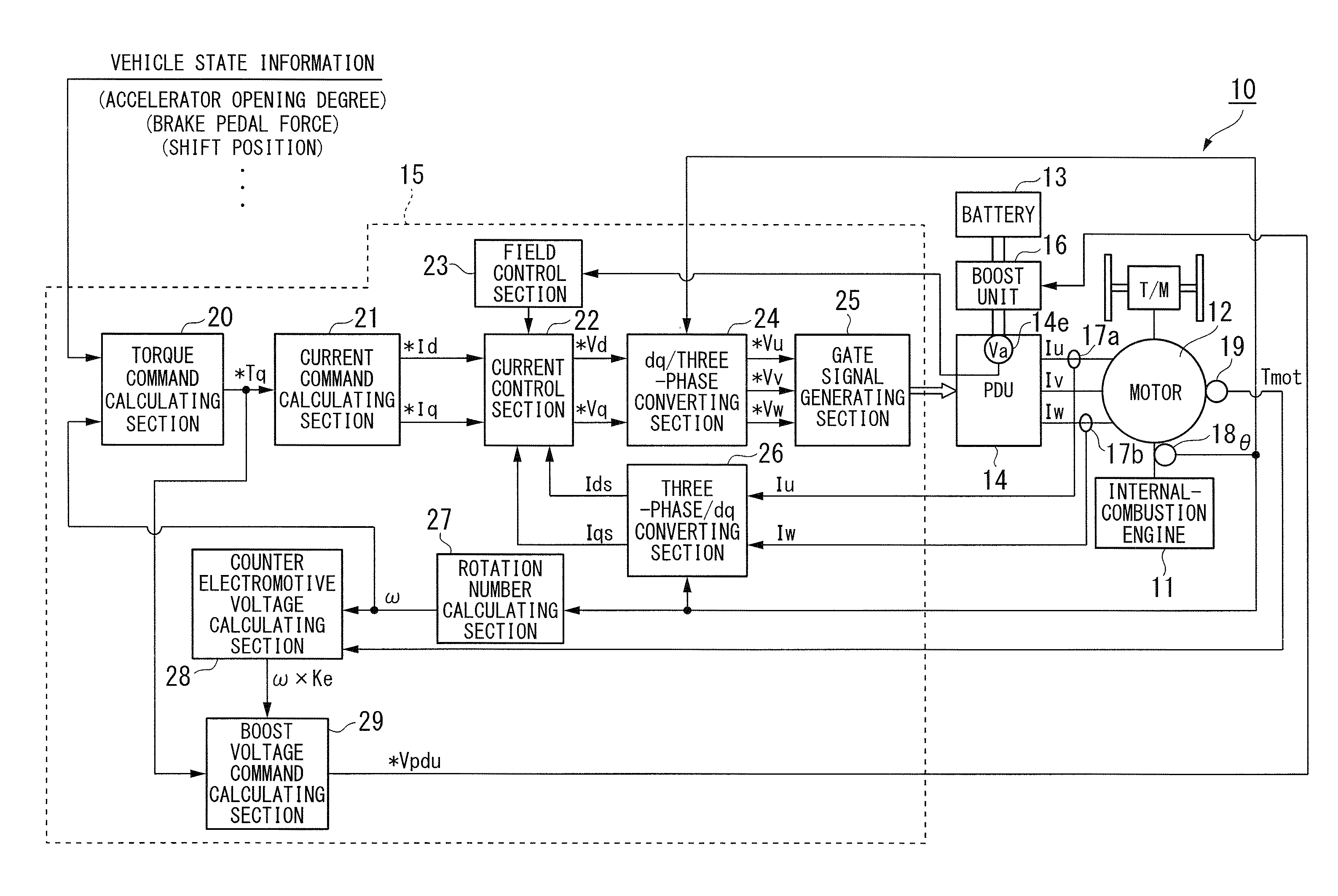
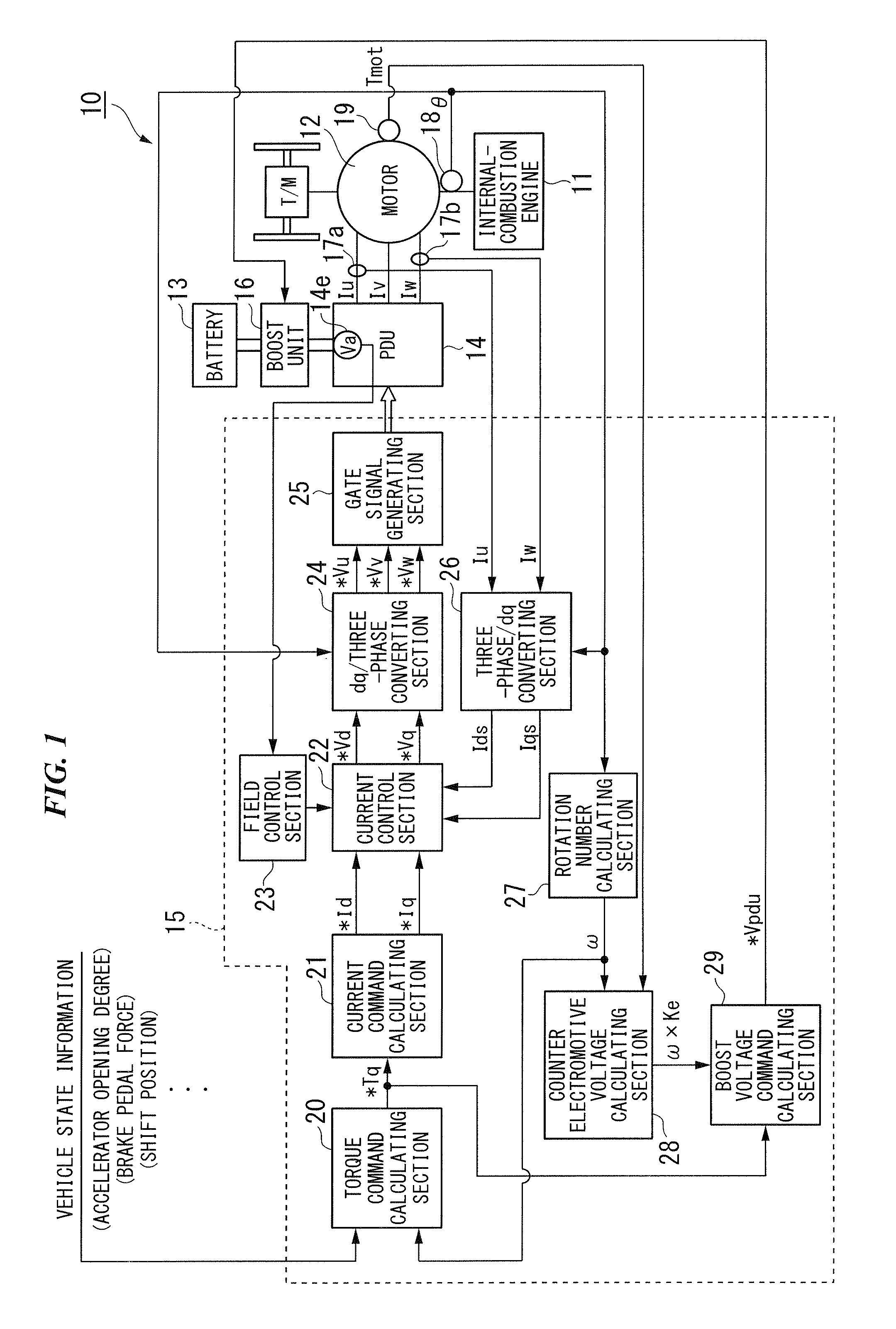
[0031]Hereinafter, a control device and a control method of a boost converter according to an embodiment of the invention is explained with reference to the accompanying drawings.

[0032]According to the embodiment, for example, the control device of the boost converter is provided in a motor control device 10 shown in FIG. 1. The motor control device 10, for example, controls driving of a brushless DC motor 12 (hereinafter, referred to as the motor 12) which is mounted as a driving source in a hybrid vehicle or the like along with an internal-combustion engine 11. The motor 12 is directly connected in series to the internal-combustion engine 11 and includes rotors (not shown) having permanent magnets used for a magnetic field and a stator (not shown) generating a rotating magnetic field rotating the rotors.

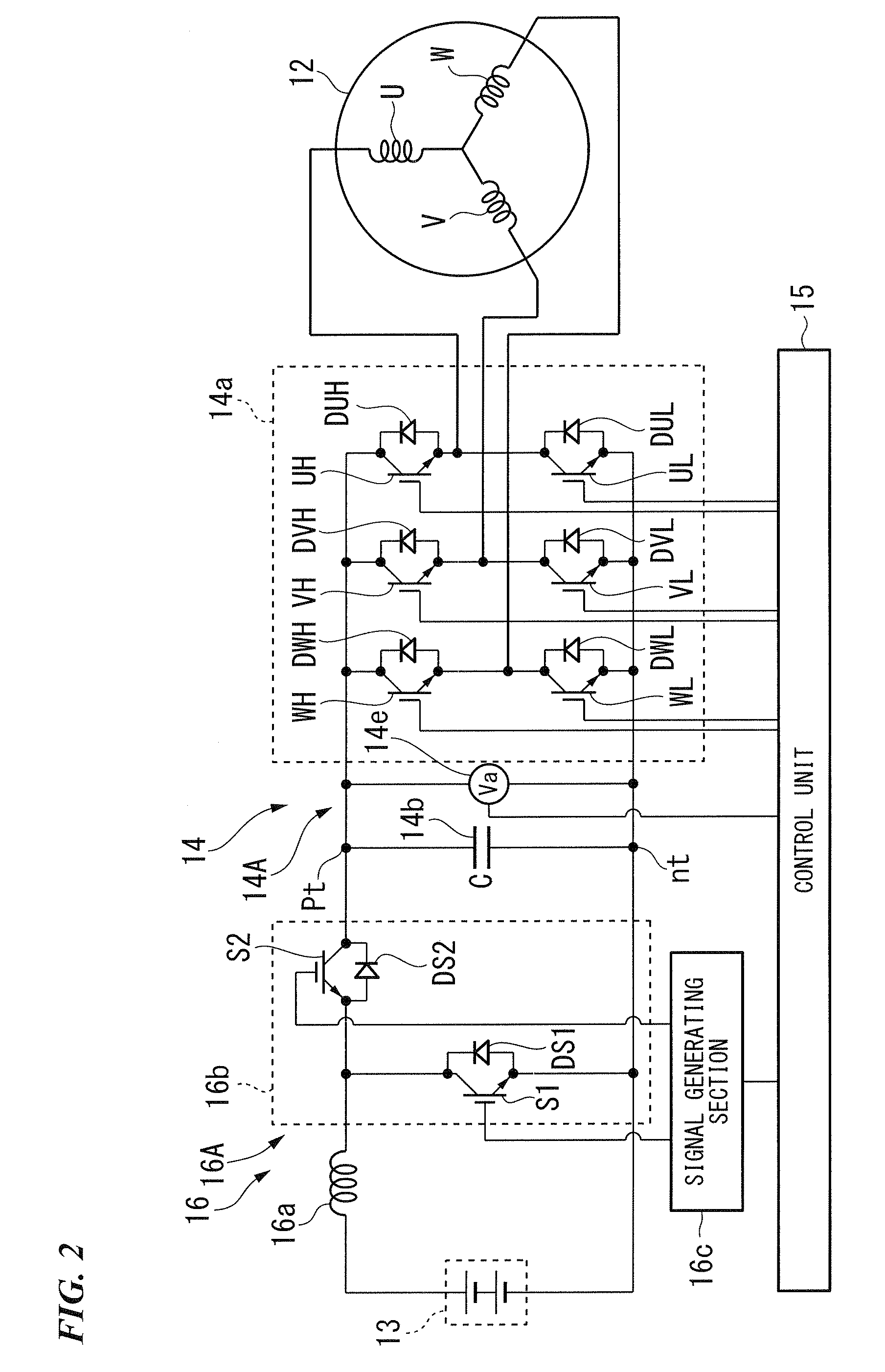
[0033]The motor control device 10 includes a power drive unit (PDU) 14 which uses a battery 13 as a DC power source, a control unit 15, and a boost unit 16. The control device of t...


PUM


Abstract

A control device of a boost converter which includes: an inverter circuit which controls switching to apply current to a stator winding of respective phases of a multi-phase brushless DC motor; and a boost circuit which is provided on an input side of the inverter circuit and has at least a reactor and a switching element, and controls ON and OFF states of the switching element of the boost circuit on the basis of a boost voltage command which is a command for boost voltage output from the boost circuit, the control device is provided with a boost voltage command setting unit which sets the boost voltage command on the basis of counter electromotive voltage of the brushless DC motor and a torque command for the brushless DC motor.

Description

BACKGROUND OF THE INVENTION[0001]Priority is claimed on Japanese Patent Application No. 2007-230260, filed on Sep. 5, 2007, the contents of which are incorporated herein by reference.FIELD OF THE INVENTION[0002]The present invention relates to a control device and a control method of a boost converter.DESCRIPTION OF THE RELATED ART[0003]In the past, for example, there was known a control device in which a current command is calculated on the basis of a torque command for an electric motor and the rotation number of the electric motor, and a voltage command is calculated by a current feedback control process based on the current command and a current detection value or by a calculation process based on the current command and a predetermined voltage equation, and a boost voltage command used to boost battery voltage VB is set so as to ensure a motor terminal voltage or IPM input voltage (for example, DC voltage of an input side of an inverter) in response to the voltage command (For ...

Claims


Application Information

Patent Timeline
Patent Type & Authority Patents(United States)
IPC IPC(8): H02P6/08B60L11/18G05F1/00H02M3/155H02M7/48H02P6/06H02P6/28H02P21/00H02P21/06H02P21/08H02P21/09H02P23/00H02P23/26
CPCB60L11/14H02P6/182H02P29/0066H02P21/00B60L2210/14B60L2220/16Y02T10/70Y02T10/643Y02T10/7077Y02T10/7225H02P29/662B60L50/16Y02T10/64Y02T10/72Y02T10/7072
Inventor KATO, TAKAYUKIKONDOH, HAJIMEMINAMIURA, KEIICHI
Owner HONDA MOTOR CO LTD
Why Eureka
Try Eureka