Power conversion control device, power conversion control method, and power conversion control program

a power conversion control and control device technology, applied in the direction of dynamo-electric converter control, motor/generator/converter stopper, electronic commutator, etc., can solve the problems of low-speed operation of low torque and substantially less responsiveness, and achieve high precision

Inactive Publication Date: 2010-12-21
UNIVERSITY OF TOKUSHIMA
View PDF22 Cites 24 Cited by
  • Summary
  • Abstract
  • Description
  • Claims
  • Application Information

AI Technical Summary

Benefits of technology

[0035]According to the present invention, a power conversion controlling apparatus that controls a power converting unit connected between a DC circuit and an AC circuit including an AC electromotive force source to exchange power between DC and AC with a switching device based on a detection signal detected by a current detector of a current flowing through the AC circuit. The power conversion controlling apparatus includes a frequency computing unit that determines an operating frequency of the power converting unit to output an operating frequency signal, an integral computing unit that determines a phase angle signal by integration from the output of the frequency computing unit to output the phase angle signal, an orthogonal biaxial transforming unit that computes a biaxial current of an active component and a reactive component by orthogonal biaxial transformation based on the detection signal of the current detector and the phase angle signal of the integral computing unit to output the biaxial current, a biaxial current setting unit that determines a command value of the biaxial current to output the command value, a biaxial current controlling unit that computes an amount of error from a difference between the output of the orthogonal biaxial transforming unit and that of the biaxial current setting unit to output an amplitude command value according to the amount of error for each biaxial component, and a PWM signal generating unit that generates a PWM signal for controlling the power converting unit based on the output of the biaxial current controlling unit and the phase angle signal of the integral computing unit, wherein the frequency computing unit determines the operating frequency of the power converting unit so as to lead the amplitude command value corresponding to a reactive component of current among the amplitude command values output by the biaxial current controlling unit to zero. Therefore, it makes effects of being able to provide a power conversion controlling apparatus that can detect an AC current without directly detecting the phase of an electromotive force source of an AC circuit by means of a sensor or the like, control the power converting unit without using the circuit constants, control the power converting unit such as an inverter easily with high precision, and be used in a wide range of fields.

Problems solved by technology

Control modes for detecting such magnetic pole position information can easily deal with high-efficiency operation and high-speed response control, but since a magnetic pole position sensor is needed, problems arise regarding reliability, workability, prices and the like.
However, though the position sensor can be eliminated, conventional control modes have problems that circuit constants of a motor must be incorporated into a control system, such conventional control modes are susceptible to transient changes, the control system will become more complicated, and the like.
However, the V / f constant control is not E / f constant control and thus, there are problems of lower torque and substantially of responsiveness during low-speed operation.
Slip frequency control type vector control or the like is used to ensure fast responsiveness, but with the control system configured by incorporating circuit constants and integrating the induction motor and control device, there are problems that the system configuration will become more complicated and its response characteristics are affected by the circuit constants.
This leads, however, to lower reliability due to a more complicated control system caused by an additional need for an AC power supply voltage detector.
Though a control technique to make a rectification operation or an inversion operation perform by computation with the detected voltage and current of the inverter without using any phase detector of the power supply voltage is known, complicated computation processing is required due to the use of circuit constants (such as the impedance and magnetic flux density of a motor).
Also, there is a problem that, for example, it is difficult to deal with wide variations in power supply frequency.

Method used


Image

  • Power conversion control device, power conversion control method, and power conversion control program
  • Power conversion control device, power conversion control method, and power conversion control program
  • Power conversion control device, power conversion control method, and power conversion control program

Examples


first embodiment

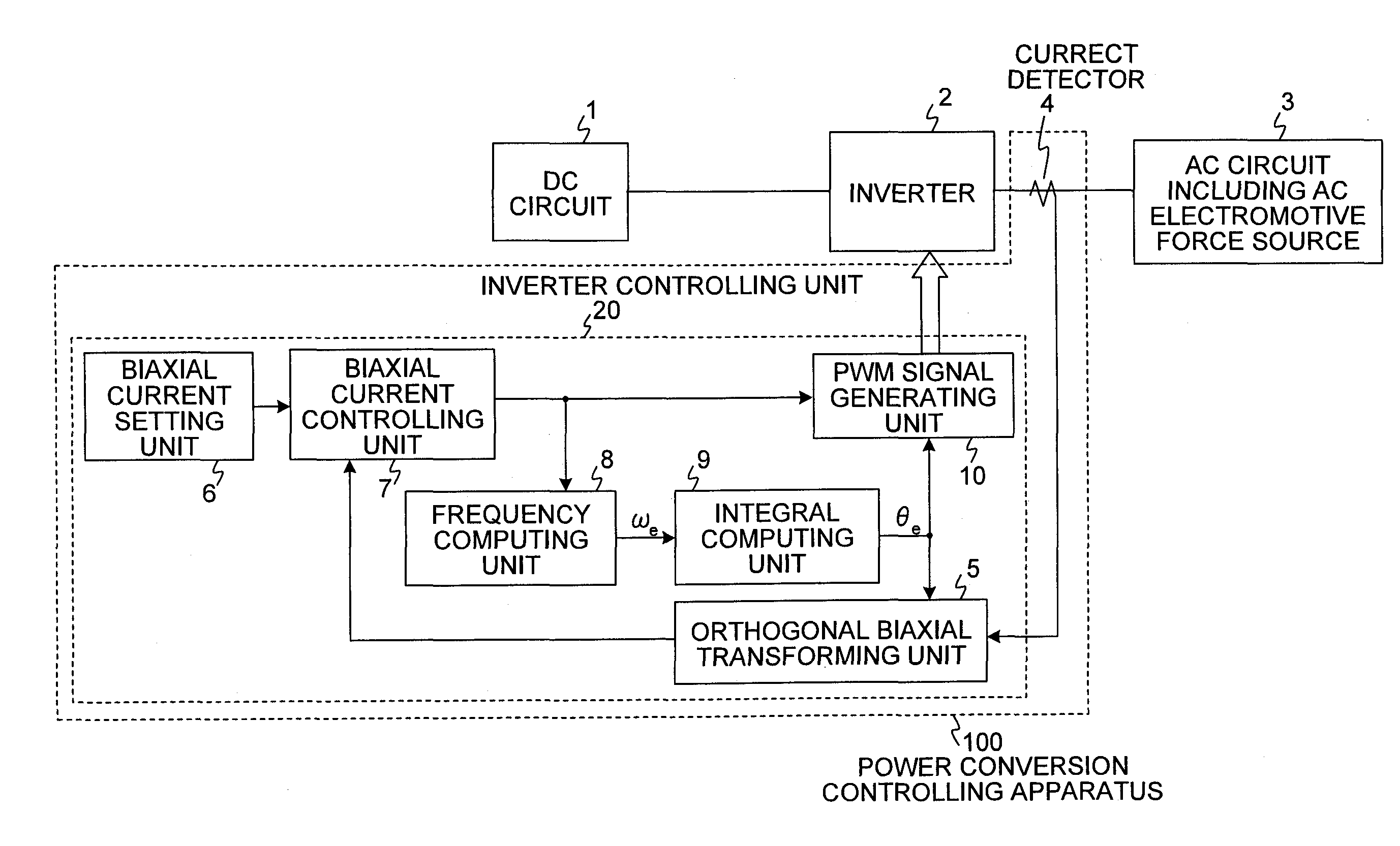
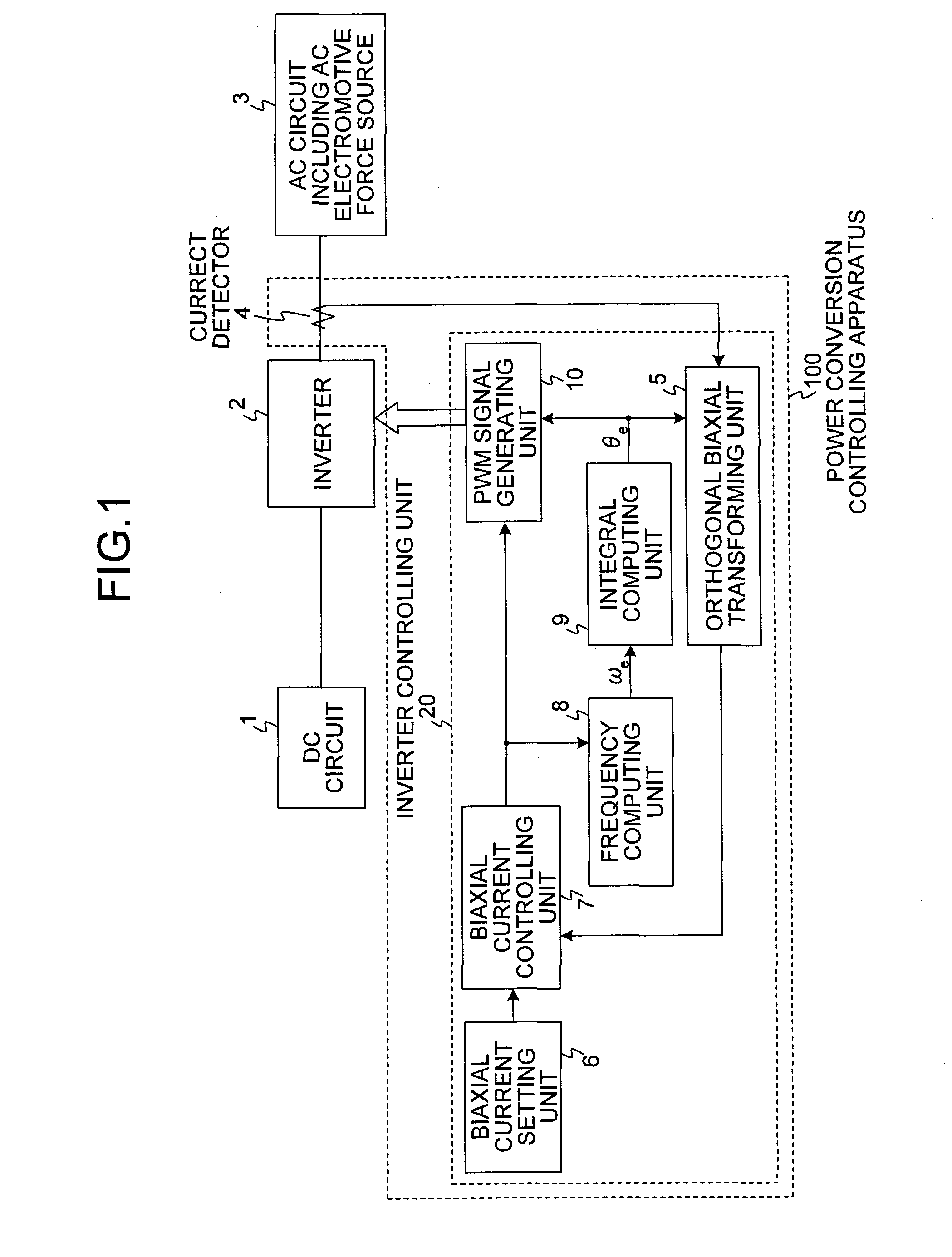
[0128]FIG. 1 is a diagram of a basic configuration of a power conversion controlling apparatus according to the present invention. The power conversion controlling apparatus according to a first embodiment is used to control an inverter that performs power conversion between DC and AC when an AC circuit has an electromotive force source.

[0129]In FIG. 1, numeral 1 is a DC circuit, numeral 2 is an inverter connected between the DC circuit 1 and an AC circuit 3 to exchange power between DC and AC with a switching device, numeral 3 is the AC circuit including the electromotive force source (hereinafter also called an “AC circuit”), and numeral 100 is a power conversion controlling apparatus. In embodiments that follow, numeral 2 is illustrated as an inverter, but numeral 2 may be an AC-DC converter that performs AC-DC conversion depending on types of the connected DC circuit 1 and the AC circuit 3.

[0130]The DC circuit 1 is a circuit including a DC power supply, a DC load, or a capacitor...

second embodiment

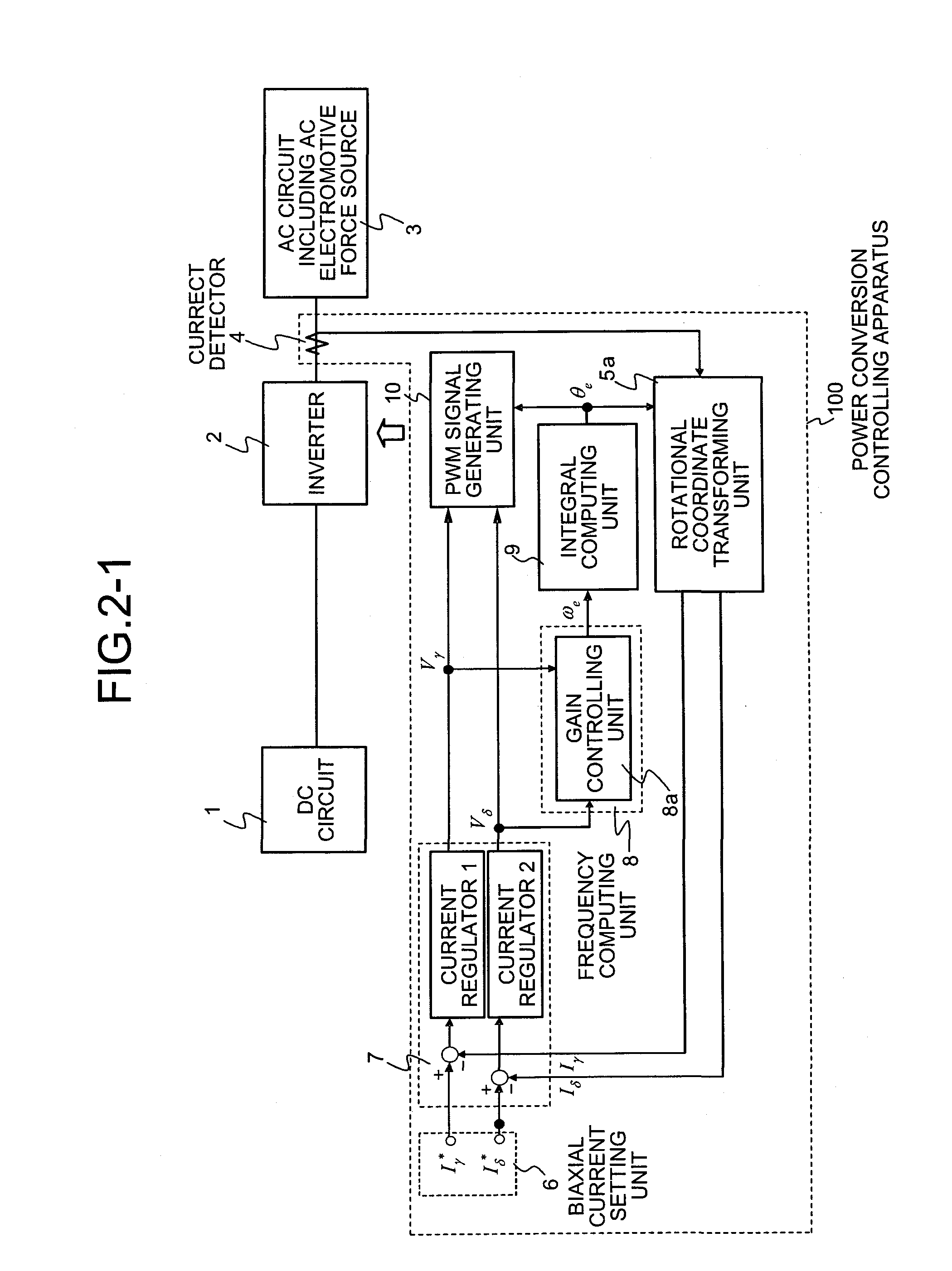
[0157]A power conversion controlling apparatus according to a second embodiment uses, in the frequency computing unit 8 (gain controlling unit 8a) of the power conversion controlling apparatus in FIG. 2-1, a value obtained by multiplying the amplitude command value corresponding to the active component of current among the amplitude command values output by the biaxial current controlling unit 7 by a gain, that obtained by multiplying a time variation reduced value of the amplitude command value corresponding to the active component of current by a gain, or a time variation reduced value of such a gain multiplied value is selected as the operating frequency ωe of the inverter 7.

[0158]More specifically, the operating frequency ωe of the inverter 2 is determined by multiplying the amplitude command value corresponding to the active component of current by a gain among the amplitude command values output from the biaxial current controlling unit 7. In this case, instead of the amplitud...

third embodiment

[0162]FIG. 8 is a diagram of an AC power conversion controlling apparatus according to a third embodiment. In FIG. 8, the same numerals are attached to components having functions equivalent to those of components in FIG. 2-1 to omit a description of common portions. The power conversion controlling apparatus according to the third embodiment has a configuration in which an impedance compensating unit is provided in the frequency computing unit 8.

[0163]In FIG. 8, the frequency computing unit 8 is provided with an impedance compensating unit 8b that outputs a compensation value for compensating for a stationary or transient voltage drop in a line impedance portion when an amplitude command value corresponding to the active component of current among the amplitude command values output by the biaxial current controlling unit 7 changes. The frequency computing unit 8 adopts a value obtained by multiplying an added value of an amplitude command value corresponding to the active componen...


PUM


Abstract

In the present invention, when configuring a control system of an inverter performing power conversion between AC and DC, a frequency computation is performed based on biaxial voltage amounts obtained through two current regulators in such a way that each of biaxial component currents obtained by detecting an AC circuit current and performing a rotational coordinate transformation matches each respective command value and phase information in synchronization with an electromotive force power supply of the AC circuit is obtained by integrating the frequency to perform the rotational coordinate transformation of the AC current and also the inverter is caused to operate by generating a PWM switching signal from the biaxial voltage amounts to perform necessary power conversion control.

Description

TECHNICAL FIELD[0001]The present invention relates to a power conversion controlling apparatus, a power conversion controlling method, and a power conversion controlling program, and more particularly, relates to a power conversion controlling apparatus, a power conversion controlling method, and a power conversion controlling program that control a power converting unit connected between a DC circuit and an AC circuit including an AC electromotive force source to exchange power between DC and AC with a switching device based on a detection signal of a current flowing through the AC circuit.BACKGROUND ART[0002]A power conversion controlling apparatus using an inverter is used very widely including application to AC motor generators from the motor control field to the generator control field, application to rectifier circuits and system interconnection inverters that exchange power between an AC power supply and a DC power supply, and the like. These usually have an electromotive for...

Claims


Application Information

Patent Timeline
Patent Type & Authority Patents(United States)
IPC IPC(8): H02P27/04H02M7/48H02P6/06H02P6/08H02P6/18H02P6/182H02P21/00H02P23/07H02P25/022H02P25/026H02P27/08
CPCH02M5/4585H02P21/0039H02P21/24H02P6/18H02P27/06
Inventor OHNISHI, TOKUOYAMANAKA, KENJIGOHDA, EIJI
Owner UNIVERSITY OF TOKUSHIMA
Why Eureka
Try Eureka