
Energy efficient and throughput enhancing extractive process for aromatics recovery

a technology of energy efficient and throughput enhancement, applied in the field of energy efficient processes for aromatics recovery, can solve the problems of consuming a significant amount of vaporization energy, high energy consumption of steam, light non-aromatic hydrocarbons, etc., and achieves satisfactory aromatic purity and recovery. , the effect of reducing total non-aromatics and easy operation of the modified ed

Inactive Publication Date: 2011-02-01
CPC CORPORATION +1
View PDF18 Cites 20 Cited by
  • Summary
  • Abstract
  • Description
  • Claims
  • Application Information

AI Technical Summary

Benefits of technology

[0008]The present invention is based in part on the discovery that substantial energy savings and enhanced throughput can be realized by making relatively simple changes to existing conventional sulfolane solvent based liquid-liquid extraction (LLE) processes. The revamping of existing facilities requires minimal capital expenditure and downtime as the conversion requires only piping changes and minor equipment adjustments.
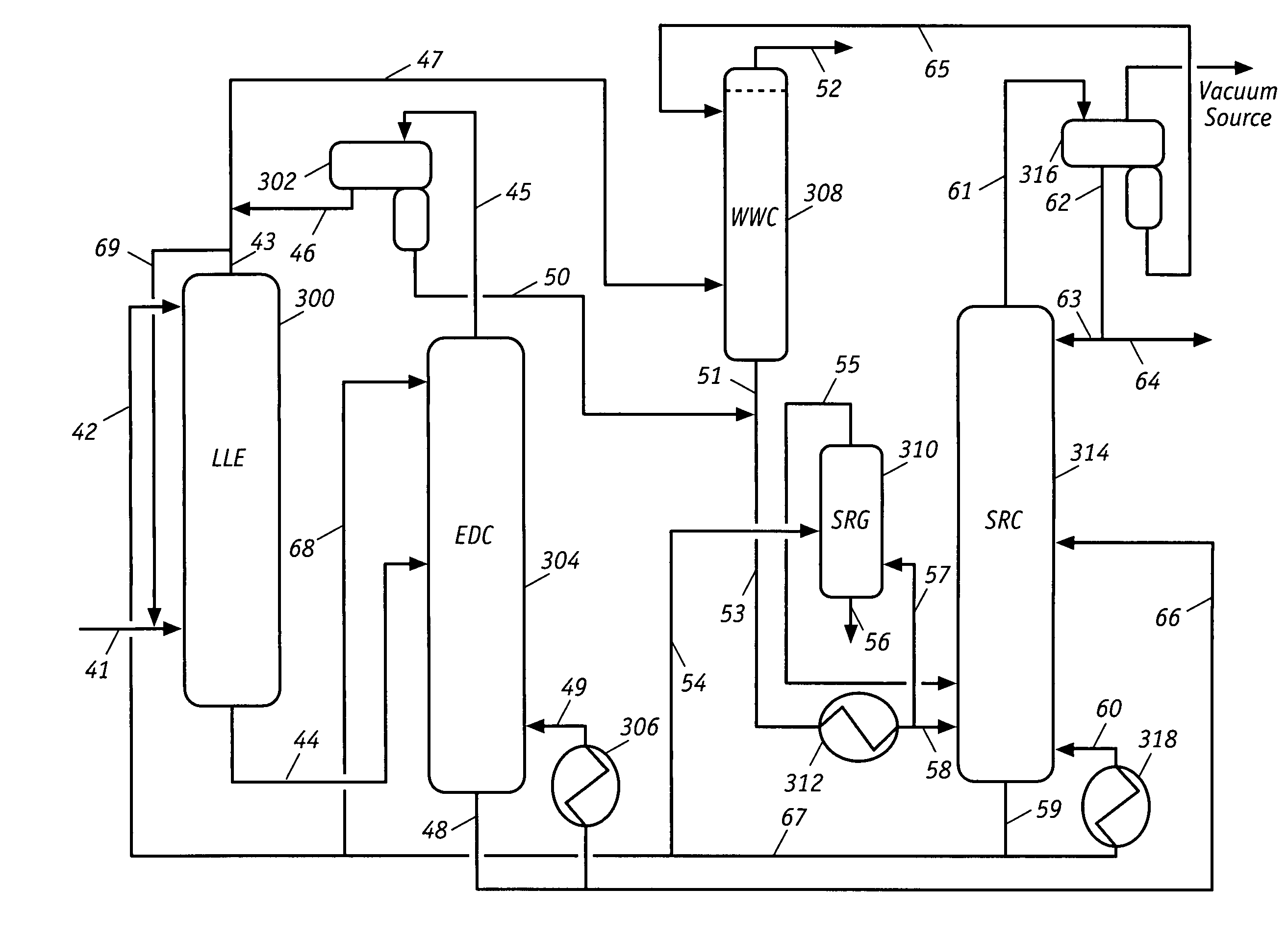
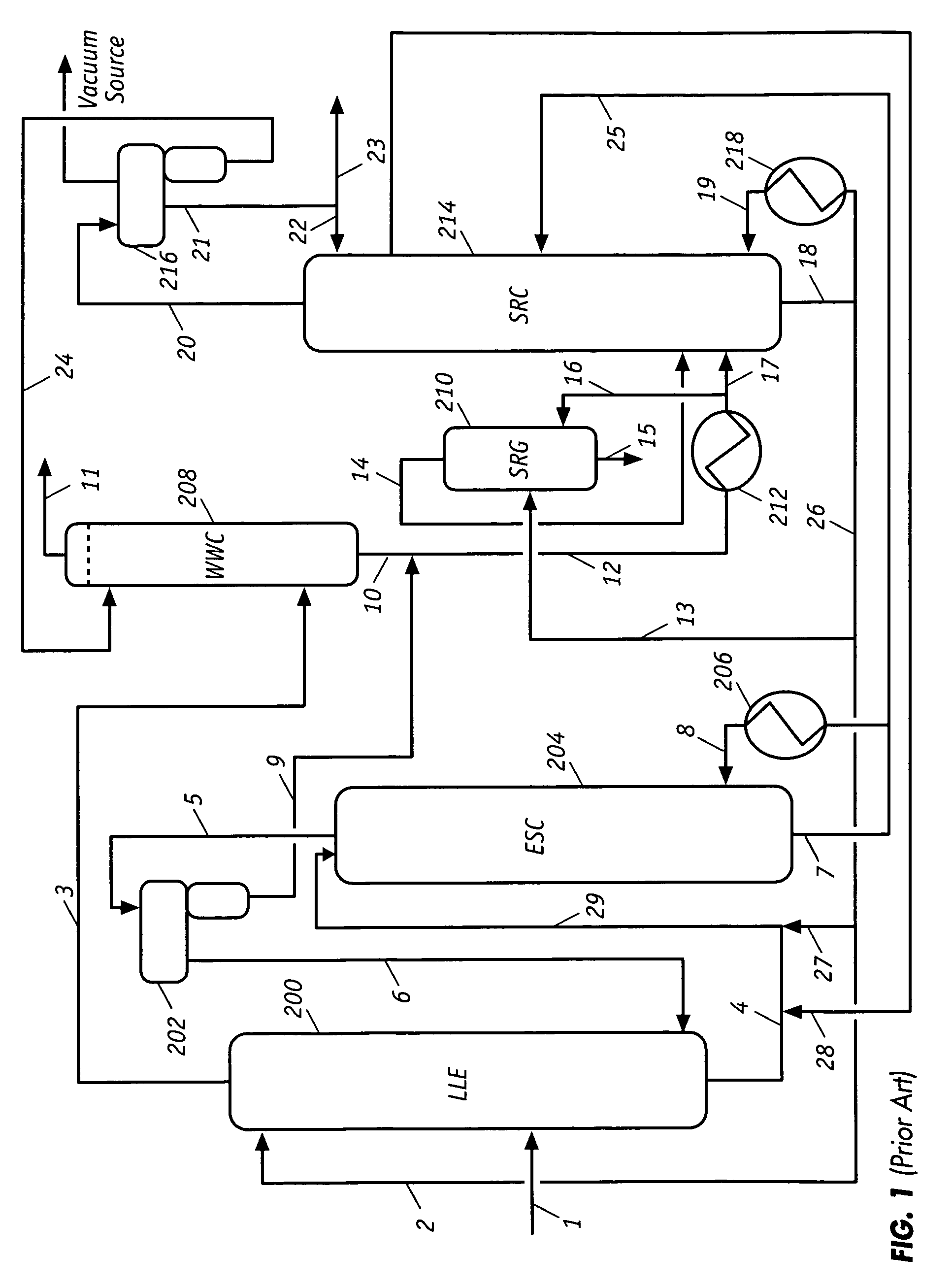
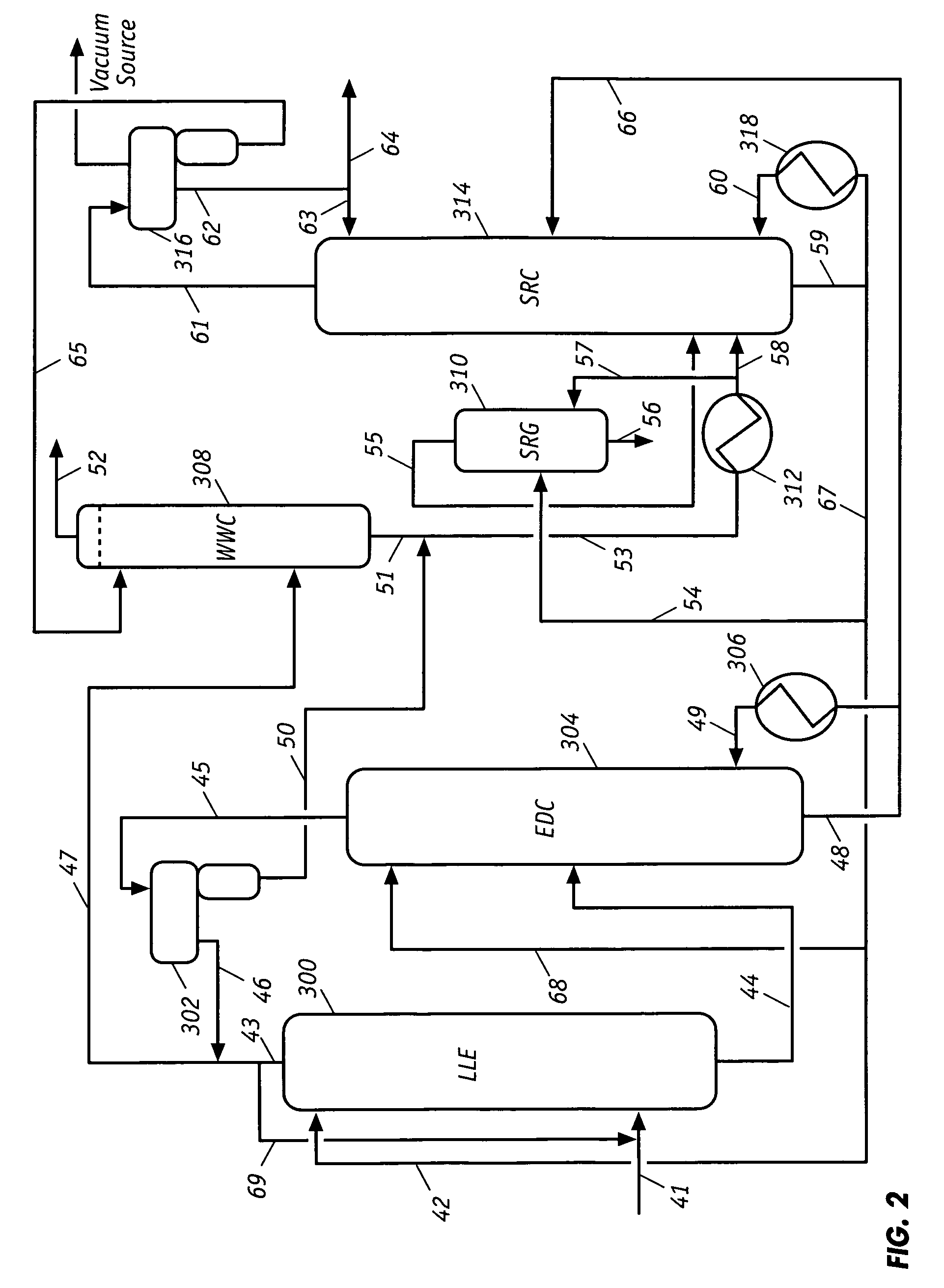
[0011]Current industrial sulfolane solvent based LLE processes for aromatic hydrocarbon recovery typically employ a liquid-liquid extraction (LLE) column, an extractive stripping column (ESC), a solvent recovery column (SRC), a raffinate water wash column (WWC), and a solvent regenerator (SRG). In implementing the inventive revamping process, one feature is to convert the existing ESC into a modified extractive distillation column (EDC) by merely implementing piping changes to the existing ESC. This simple piping modification, in effect, incorporates the advantages of both the LLE and ED into one process to generate substantial energy savings as well as achieve significant throughput increase for an existing liquid-liquid extraction process for aromatic hydrocarbon recovery. Another feature of the present invention is the elimination of the energy consuming and troublesome LLE reflux, so that the LLE column in the new configuration is operated without a reflux.
[0012]In a preferred embodiment, the LLE column is operated under conditions such as to reject all C8+ non-aromatics and most of the C7 non-aromatics and to allow only C5-C6 non-aromatics and small amounts of C7 non-aromatics to be extracted along with the aromatics into the extract phase. This expected phenomenon is based on the realization that heavier non-aromatics have relatively lower polarity and less affinity with the extractive solvent, and are, therefore, easier to be rejected by the solvent in an LLE column. In operation of the inventive process, the extract phase, which contains the solvent, all the (C6-C8+) aromatics, only C5-C6 non-aromatics, and minor amounts of C7 non-aromatics, is withdrawn from the bottom of the LLE column and transferred to the middle portion of the modified EDC (formerly ESC) as the hydrocarbon feed.
[0014]In order to achieve satisfactory aromatic purity and recovery in the modified EDC, the solvent needs to keep essentially all benzene (the lightest aromatic) in the EDC bottom and virtually all of the heaviest non-aromatics is driven into the overhead of the EDC. In the inventive process, operation of the modified EDC is quite easy since essentially all of the heavy non-aromatics are removed from the EDC feed by the front-end LLE column, thus allowing only C5-C6 non-aromatics with minor amounts of C7 non-aromatics to be present in the feed to the EDC. This is crucial because the existing ESC normally has only 40 to 45 separating trays (or roughly 16 to 18 theoretical trays), which is adequate for the EDC operation when only light non-aromatics is present in the hydrocarbon feedstock. In the absence of heavy non-aromatics and greatly reduced total non-aromatics in the feed, the energy requirement of the modified EDC is substantially reduced as compared to the original ESC.
[0015]Since non-aromatics have very limited solubility in the solvent, such as sulfolane, they tend to generate undesirable two liquid phases in the upper portion of the modified EDC. A further feature of the inventive process is to reduce the two liquid phase region in the upper portion of the modified EDC to thereby enhance column performance and operation. This is achieved by greatly reducing the level of non-aromatics in the EDC feed.
[0016]Another important feature of the invention is the elimination of the reflux to the top of the modified EDC to further: (1) reduce energy consumption of the column; (2) reduce vapor loading of the upper portion of the column, thereby, increasing the column throughput; and (3) reduce the two liquid phase region in the upper portion of the column, since the reflux contains essentially pure non-aromatics. In an ordinary distillation column, the overhead liquid reflux is essential for generating the necessary liquid phase in the rectifying section of the column which contacts the uprising vapor phase from tray-to-tray for separating the key components in the feed mixture. Depending upon the particular application, normal reflux-to-distillate ratio of an ordinary distillation column is approximately 1 to 20. In the modified EDC, however, the liquid phase in the rectifying section is the nonvolatile, polar solvent, which preferentially absorbs the more polar components (the aromatics) from the uprising vapor phase. This allows the less polar components (the non-aromatics) vapor to ascend to the top of the EDC. It has been demonstrated in a three-meter diameter EDC for benzene, toluene, and xylene (BTX) aromatics recovery that adding reflux to the EDC has no effect in enhancing the separation. In other words, adding reflux to the modified EDC has no effect on the purity and recovery of the overhead product (the non-aromatic raffinate).

Problems solved by technology

However, a major drawback of this process is the high energy (steam) consumption of the ESC, in which all the overhead condensate is recycled to the lower portion of the LLE column as the reflux.
Another significant drawback of current ESC operations is that light non-aromatic hydrocarbons (C5-C6), due their higher affinities with the solvent, are continuously accumulated in a closed loop between the top of ESC and the bottom of the LLE column with no way out but consuming a significant amount of vaporization energy.
This large reflux operation not only requires high energy but also creates a bottleneck at the ESC and reduces throughput of the LLE process.
Most of these schemes which are based on heat integration, such as by using heat exchangers between process streams, pressure reduction devices between process vessels, and the like, have achieved only limited success but with significant increase in equipment costs.

Method used


Image

  • Energy efficient and throughput enhancing extractive process for aromatics recovery
  • Energy efficient and throughput enhancing extractive process for aromatics recovery
  • Energy efficient and throughput enhancing extractive process for aromatics recovery

Examples


example 1

Comparative

Base Case

[0036]Referring to FIG. 1, one thousand (1,000) Kg / Hr of the hydrocarbon feed at 75° C. and 6.4 Bar (pressure) are fed continuously to the middle portion of LLE column 200 via line 1. This stream contains approximately 25 wt % benzene, 19 wt % toluene, 17 wt % C8 aromatics, 0.5 wt % C9+ aromatics, and 39 wt % C5-C9+ non-aromatics. Thirty six hundred (3,600) Kg / Hr of the sulfolane solvent containing 0.8 wt % water at 81° C. and 6.4 Bar are introduced to the upper portion of LLE column 200 via line 2 entering the column at a location below the interface between the raffinate phase and extract phase. Multi-stage counter-current liquid-liquid extraction occurs in LLE column 200 at a temperature of 80° C. and a pressure of 6.4 Bar. The raffinate stream, with only 0.27 wt % C8+ aromatics and essentially free of benzene and toluene, is withdrawn from the top of the LLE column and transferred to the lower portion of the WWC via line 3 at a flow rate of 397 Kg / Hr. The ext...

example 2

The Inventive Process

Revamped Case

[0041]This example demonstrates that the energy consumption of the ESC is substantially reduced by converting it into a modified EDC that is operated without reflux and by totally eliminating the reflux from the ESC to the LLE column. In addition to a large reduction in energy consumption, throughput of the revamped process consisting of the LLE and the modified EDC is also significantly increased. Because the revamp can be accomplished with minor piping modifications, the user has the flexibility of reverting to the original process configuration where necessary.

[0042]Referring to FIG. 2, one thousand (1,000) Kg / Hr of hydrocarbon feed at 75° C. and 6.4 Bar is fed continuously to a location near the bottom of LLE column 300 via line 41. This stream has essentially the same composition as that of the LLE feed in example 1. Twenty one hundred (2,100) Kg / Hr of sulfolane solvent containing 0.8 wt % water at 81° C. and 6.4 Bar are introduced to the upper...


PUM

PropertyMeasurementUnit
temperatureaaaaaaaaaa

Abstract

An energy efficient, high throughput process for aromatics recovery can be readily implemented by revamping existing sulfolane solvent extraction facilities, or constructing new ones, so as to incorporate unique process operations involving liquid-liquid extraction and extractive distillation. Current industrial sulfolane solvent based liquid-liquid extraction processes employ a liquid-liquid extraction column, an extractive stripping column, a solvent recovery column, a raffinate wash column, and a solvent regenerator. The improved process for aromatic hydrocarbon recovery from a mixture of aromatic and non-aromatic hydrocarbons requires transformation of the extractive stripping column into a modified extractive distillation column. The revamping incorporates the unique advantages of liquid-liquid extraction and extractive distillation into one process to significantly reduce energy consumption and increase process throughput. The revamp entails essentially only piping changes and minor equipment adjustments of the original liquid-liquid extraction facility, and is therefore, reversible.

Description

CROSS-REFERENCE TO RELATED APPLICATIONS[0001]This application claims priority to provisional patent application No. 61 / 123,800 which was filed on Apr. 10, 2008.FIELD OF THE INVENTION[0002]The present invention is directed to energy efficient processes for aromatics recovery that require significantly less energy but achieve substantially higher throughput relative to current sulfolane solvent based liquid-liquid extraction techniques. The improved process that can be readily implemented by revamping existing sulfolane solvent extraction facilities, or constructing a new one, so as to incorporate unique process operations involving liquid-liquid extraction and extractive distillation.BACKGROUND OF THE INVENTION[0003]Liquid-liquid extraction (LLE) using sulfolane with water as the extractive solvent is the most important commercial process for purifying the full-range (C6-C8) of aromatic hydrocarbons from petroleum streams, including reformate, pyrolysis gasoline, coke oven oil, and c...

Claims


Application Information

Patent Timeline
Patent Type & Authority Patents(United States)
IPC IPC(8): C10G21/28
CPCC10G21/06C10G21/28C10G2300/4056
Inventor LEE, FU-MINGWU, KUANG-YEUCHIU, TSUNG-MINCHEN, ZONG-YINGHWANG, JYH-HAURLIN, TZONG-BINSHEN, HUNG-CHUNGKUO, TUNG-HSIUNGWU, YU-MING
Owner CPC CORPORATION
Learn More