Electron beam measurement apparatus
a technology of electromagnetic radiation and measurement apparatus, applied in the direction of instruments, semiconductor/solid-state device testing/measurement, image enhancement, etc., can solve the problem of unclear how to measure a sampl
- Summary
- Abstract
- Description
- Claims
- Application Information
AI Technical Summary
Benefits of technology
Problems solved by technology
Method used
Image
Examples
first embodiment
[0036]First, a basic configuration of an electron beam measurement apparatus according to the present invention will be described.
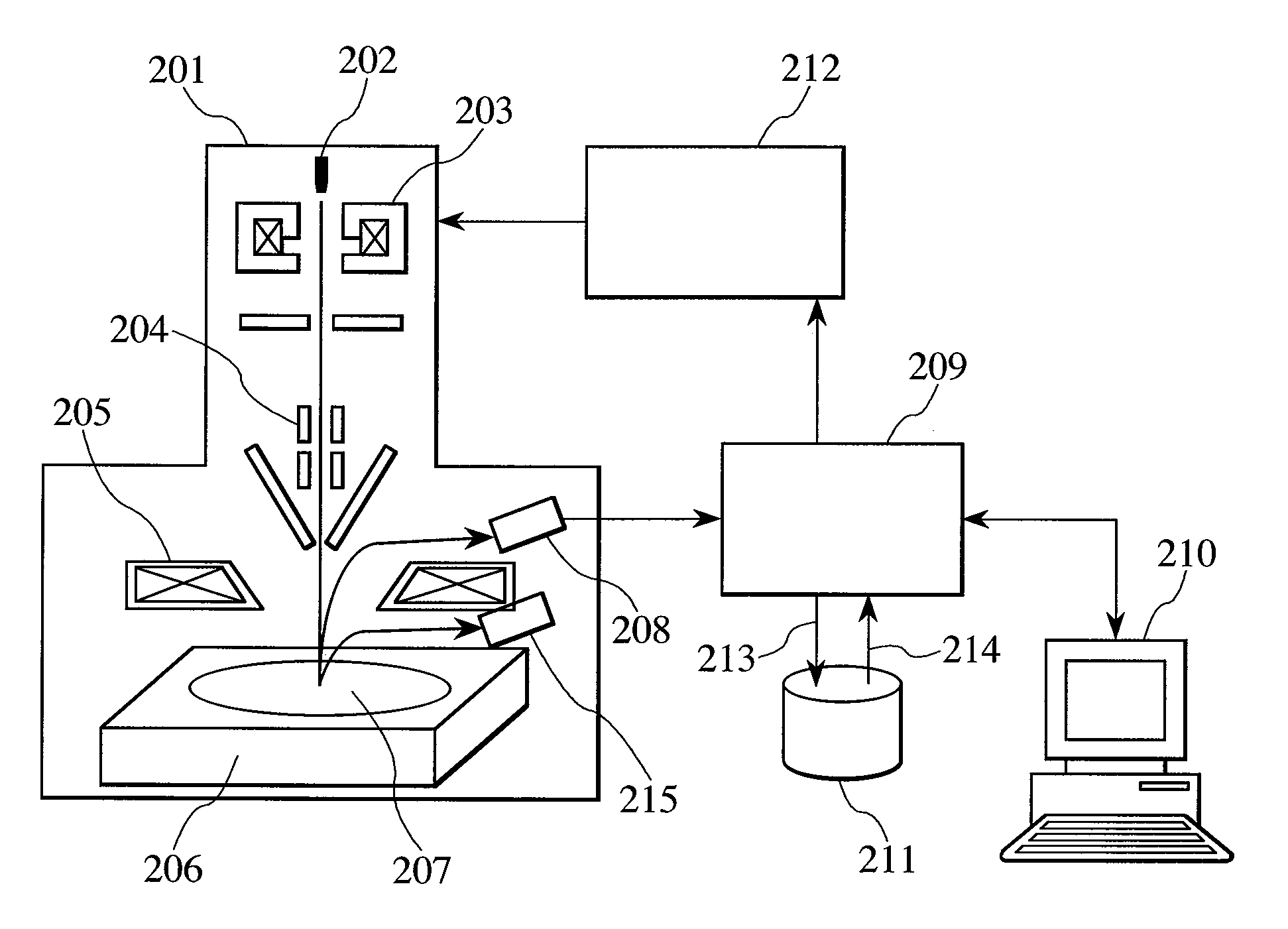
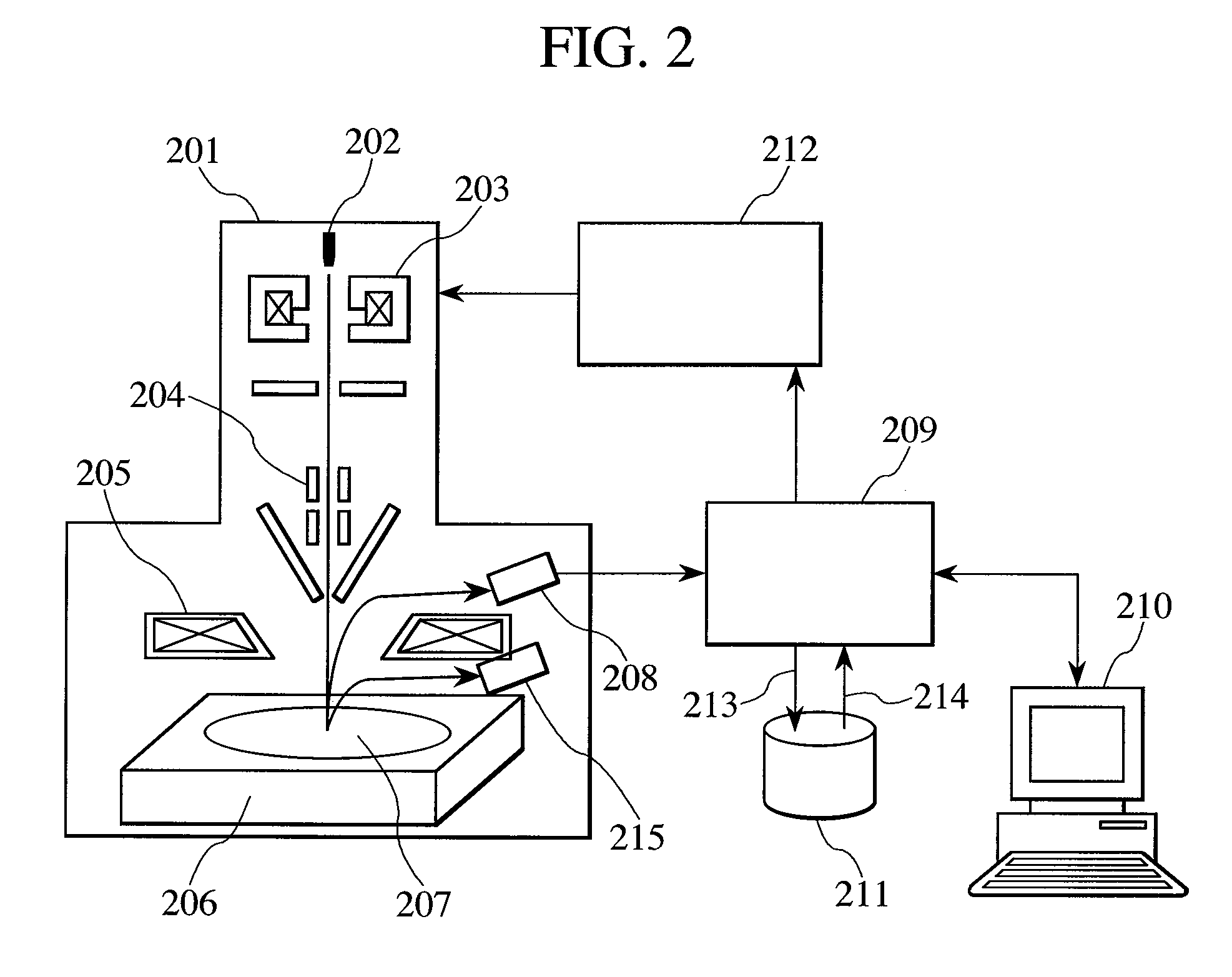
[0037]FIG. 2 is a diagram showing the basic configuration of the electron beam measurement apparatus according to the present invention. The electron beam measurement apparatus has an electron optical system 201, a secondary electron detector 208, a reflective electron detector 215, a computing unit 209, a display unit 210, a storage unit 211, and an electron optical system controller 212. The electron optical system 201 uses a condenser lens 203, a deflector 204 and an objective lens 205 to irradiate a sample (wafer) 207 placed on a stage 206 with an electron beam emitted by an electron gun 202 and scan the sample. The secondary electron detector 208 is adapted to detect the intensity of a charged particle (secondary electron) secondarily generated from the sample 207 by the irradiation of the electron beam. The reflective electron detector 215 is adapte...
second embodiment
[0048]FIG. 5 is a flowchart of the measurement according to a second embodiment of the present invention. In the measurement shown in FIG. 5, after an SEM image is acquired, patterns are classified into groups by comparing the SEM image with design data, in step 501. In the pattern (shown in FIG. 9) having lines and spaces which are alternately arranged, matching of the pattern may be performed with a single pitch shifted. This measurement method shown in FIG. 5 is suitable for a logic LSI having a complex pattern. It can be considered that a combination of this measurement method shown in FIG. 5 with the classification method based on the brightness in the first embodiment is effective.
[0049]According to the present embodiment, the contour of a portion of each pattern is detected, and the length of the contour is evaluated, to inspect a hot spot (which is a location at which a defect is likely to occur). As a result, detection sensitivity can be improved in the present embodiment, ...
third embodiment
[0050]FIG. 6 is a flowchart showing a measurement according to a third embodiment of the present invention. In the present embodiment, a plurality of images is used. After the sample is moved to a location defined by coordinates of an area to be imaged, a single SEM image is acquired under a first condition in step 601, and a single SEM image is acquired in step 602 under a second condition different from the first condition. Under the first condition, the number of times of scanning of an observation area is eight. Under the second condition, the number of times of television scanning of the observation area is 32. The reason for acquiring the images under the conditions different from each other is that the intensity of a signal coming from the processed layer is low. Thus, the number of times of the scanning under the second condition is 32 in order to improve a signal-to-noise ratio. The intensity of a signal coming from the hard mask layer is too high when the image acquisition...
PUM
| Property | Measurement | Unit |
|---|---|---|
| wavelength | aaaaa | aaaaa |
| wavelength | aaaaa | aaaaa |
| electron beam measurement | aaaaa | aaaaa |
Abstract
Description
Claims
Application Information
 - R&D
- Intellectual Property
- Life Sciences
- Materials
- Tech Scout
- Unparalleled Data Quality
- Higher Quality Content
- 60% Fewer Hallucinations
Browse by: Latest US Patents, China's latest patents, Technical Efficacy Thesaurus, Application Domain, Technology Topic, Popular Technical Reports.
© 2025 PatSnap. All rights reserved.Legal|Privacy policy|Modern Slavery Act Transparency Statement|Sitemap|About US| Contact US: help@patsnap.com


