System and method of waste heat recovery and utilization

a waste heat recovery and waste heat technology, applied in the field of internal combustion engine improvement, can solve the problems of lubricant, prolonging the combustion duration in the power stroke, prolonging the life of the engine components, etc., to facilitate the recovery of waste heat, improve the other operating conditions of the engine, and improve the fuel consumption efficiency of the engine

Inactive Publication Date: 2011-02-22
PRIMLANI INDRU J
View PDF32 Cites 18 Cited by
  • Summary
  • Abstract
  • Description
  • Claims
  • Application Information

AI Technical Summary

Benefits of technology

The present disclosure provides a system and method that facilitates recovering waste heat generated in an engine, such as an internal combustion engine, to improve the fuel consumption efficiency of the engine, and improve other operating conditions of the engine. Some embodiments increase the thermal efficiency of the engine, which when incorporated on a large scale on numerous engines in portable and / or stationary applications, can significantly contribute to reducing global warming and reducing air pollution emissions.

Problems solved by technology

Some embodiments result in the engine producing higher torque than existing engines at lower revolutions per minute, prolonging the life of the engine and lubricants therein, and extending combustion duration in the power stroke.
Furthermore, engine component life is prolonged due to extraction of waste heat from the engine resulting in a cooler engine compartment.

Method used


Image

  • System and method of waste heat recovery and utilization
  • System and method of waste heat recovery and utilization
  • System and method of waste heat recovery and utilization

Examples


Embodiment Construction

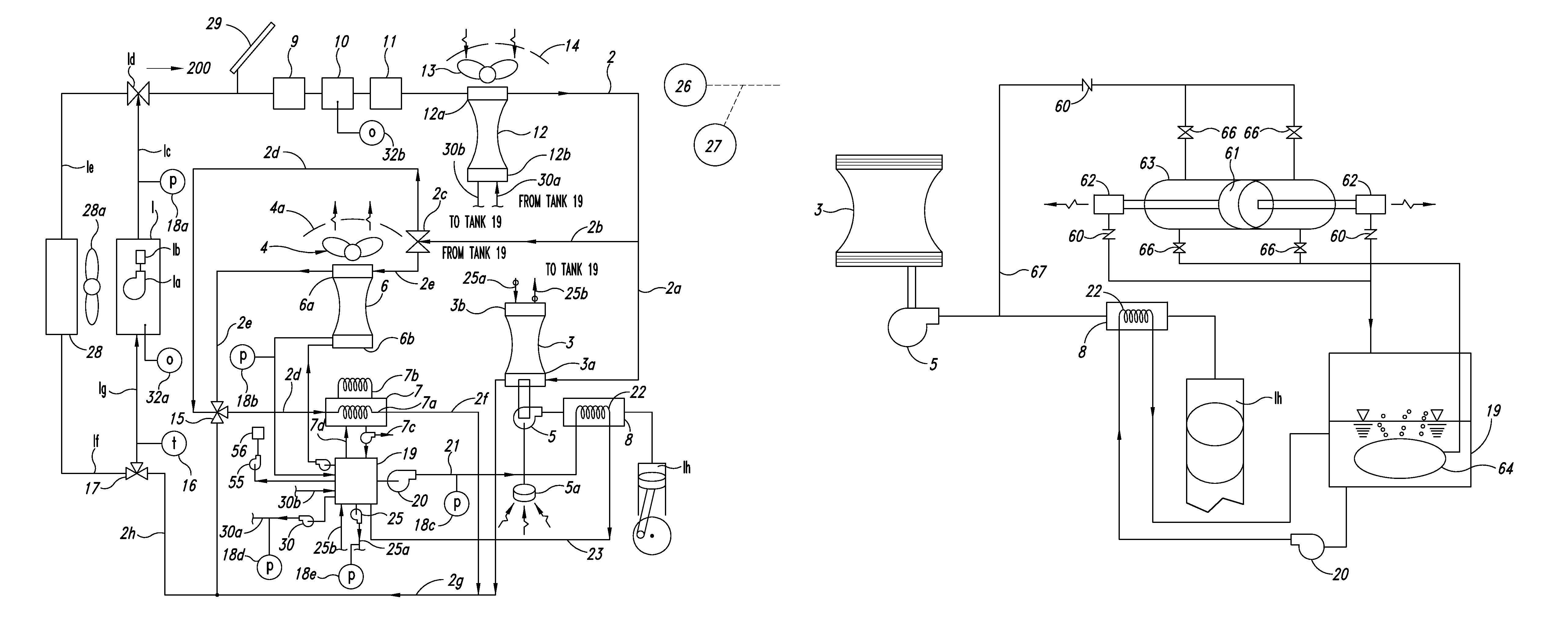
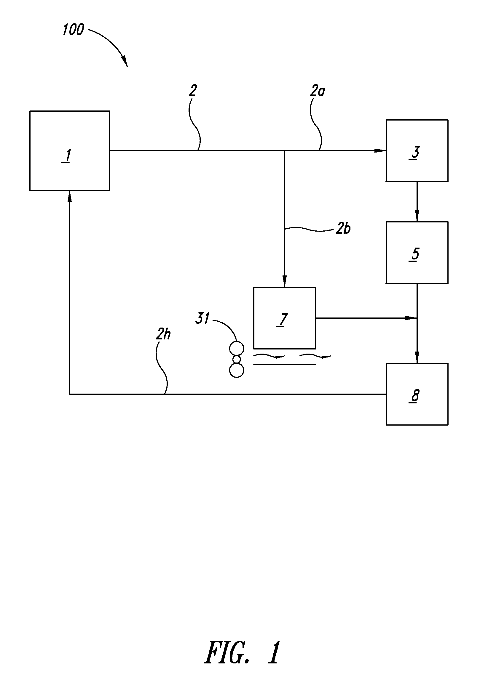
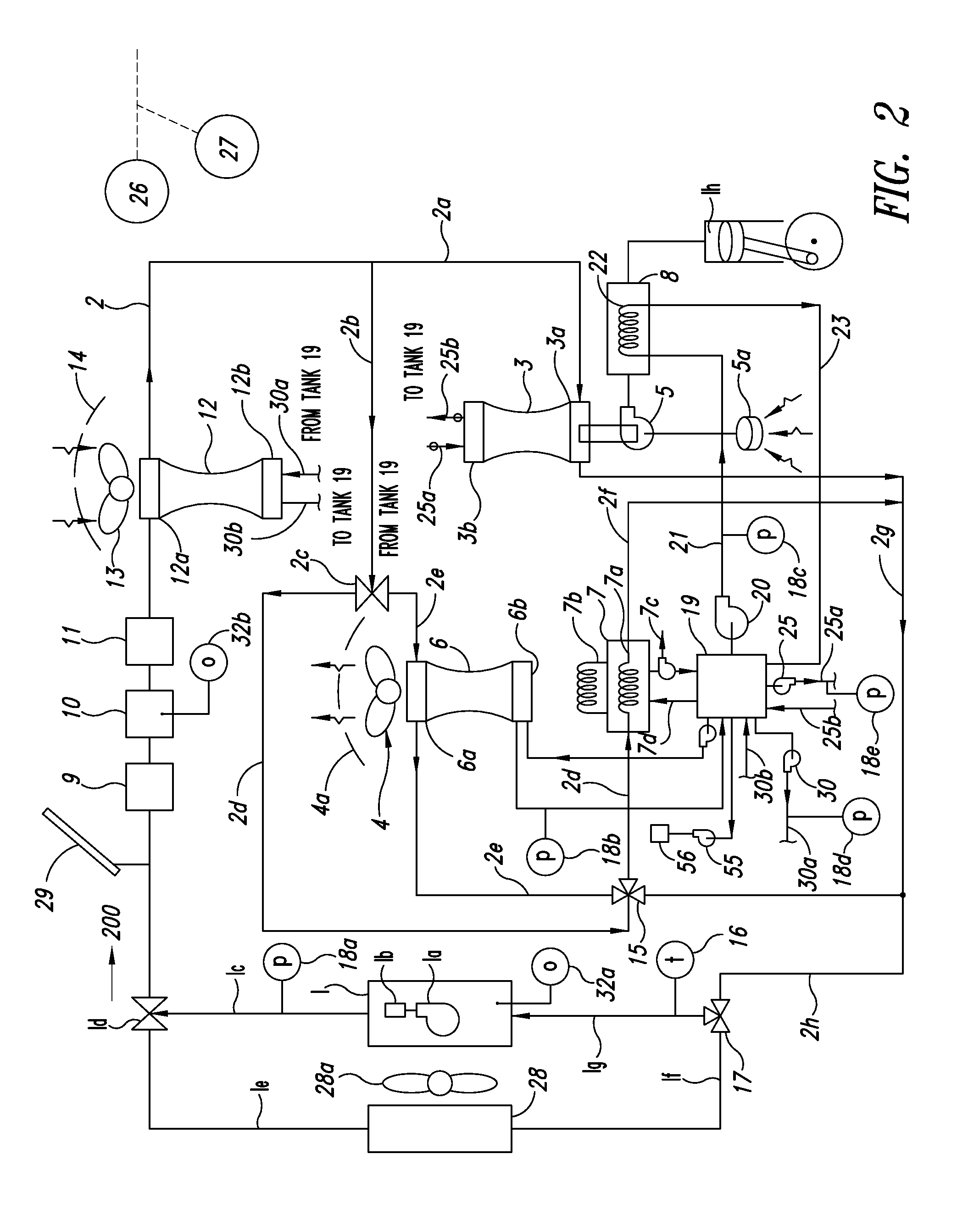
FIG. 1 illustrates a waste heat recovery and utilization system 100 according to one embodiment. The system 100 includes an internal combustion engine 1, a non-combustion engine 3, a compressor 5, and a cooling system or apparatus 7. In one aspect, the non-combustion engine 3 can include a Stirling engine, and the cooling system 7 can include a chiller. For clarity of description and convenience, reference to non-combustion engines will hereinafter be made by “Stirling engine,” without any intention to limit the present disclosure or to exclude other suitable non-combustion engines. Similarly, reference to cooling systems or apparatuses will hereinafter be made by “chiller,” without any intention to limit the present disclosure or to exclude other suitable cooling devices.

In one aspect, the system 100 further includes a waste heat loop 2 configured to recover heat from the engine 1 and route it to the Stirling engine 3.

The waste heat loop 2 includes a heat transfer fluid, such as wa...


PUM


Abstract

A waste heat recovery system is provided for an internal combustion engine having a piston, a cylinder and an intake manifold, significantly improving gas mileage efficiency without reliance on alternative fuels. The system includes a heat loop having a heat transfer fluid, a compressor in fluid communication with the intake manifold to supply compressed air thereto, a Stirling engine operated and optimized via thermal communication with the heat loop, and operatively coupled to the compressor. The system includes a chiller in thermal communication with the heat loop, and with the intake manifold to cool the compressed air communicate to the cylinder. The system may include additional Stirling engines operating other devices, or being operated by a device, such as a propeller. A vehicle can incorporate the system and route fluid to and from a radiator. The system can be used in both portable and stationary applications.

Description

BACKGROUND1. Technical FieldThe present application is generally related to improvements in internal combustion engines, and particularly, to a waste heat recovery system and method for internal combustion engines that use pistons.2. Description of the Related ArtImprovements in vehicle operation efficiencies revolve around a number of parameters, including environmental impact, performance, and fuel type. Recent developments have primarily been made in the field of hybrid fuel technology, in an effort to improve vehicle fuel efficiency and reduce pollution generation from operation of the vehicle. Hybrid or alternative fuel vehicles typically rely on electrical, or fuel-cell technology. Hybrid fossil fuel-electric vehicles, however, have thus far only reached limited improvements in fuel consumption efficiency. Furthermore, hybrids and fuel-cell vehicles require high capital costs. Moreover, fuel-cell technology is not yet developed to a point to be sufficiently efficient for the c...

Claims


Application Information

Patent Timeline
Patent Type & Authority Patents(United States)
IPC IPC(8): F01K3/00F01K23/14F01K7/34F01K23/06
CPCF01K15/02F01K23/065
Inventor PRIMLANI, INDRU J.
Owner PRIMLANI INDRU J
Why Eureka
Try Eureka