Method for controlling at least one sheathed-element glow plug in an internal combustion engine and engine controller

a technology of internal combustion engine and glow plug, which is applied in the direction of electric control, machines/engines, lighting and heating apparatus, etc., can solve the problems of increasing emissions and achieve the effect of greatly reducing exhaust emissions

Inactive Publication Date: 2011-03-08
ROBERT BOSCH GMBH
View PDF7 Cites 1 Cited by
  • Summary
  • Abstract
  • Description
  • Claims
  • Application Information

AI Technical Summary

Benefits of technology

[0013]An object of the present invention is to provide a method which provides optimal combustion properties of an internal combustion engine while at the same time being inexpensive and easily implementable. It is also an object of the present invention to provide a corresponding engine controller.
[0015]An important point of the method according to the present invention is that in certain operating states, the combustion properties of the internal combustion engine reach an optimum and exhaust emissions are reduced significantly when the temperature of the sheathed-element glow plug is regulated as a function of operating parameters of the internal combustion engine.
[0016]According to this, an advantageous specific embodiment of the present invention provides for the at least one operating parameter to include a rotational speed of the internal combustion engine. Thus, emissions may be reduced significantly when there is a change in pressure, in particular when the engine cools down. White smoke and / or black smoke in the transition from coasting to normal driving operation may be reduced in particular. It has been found that the combustion chambers cool down during prolonged coasting or prolonged downhill driving when little or no fuel is being injected. If a large quantity of fuel is then injected, this is associated with increased emissions. This cooling is therefore counteracted by triggering of the sheathed-element glow plugs accordingly.
[0023]The at least one temperature change variable is preferably differentiated by characteristic bits at the interface. This reduces the data volume required for the calculation.
[0025]An important point of the engine controller according to the present invention is that the combustion properties of the internal combustion engine reach an optimum in certain operating states and exhaust emissions are greatly reduced when the temperature of the sheathed-element glow plug is regulated as a function of operating parameters of the internal combustion engine.

Problems solved by technology

If a large quantity of fuel is then injected, this is associated with increased emissions.

Method used


Image

  • Method for controlling at least one sheathed-element glow plug in an internal combustion engine and engine controller
  • Method for controlling at least one sheathed-element glow plug in an internal combustion engine and engine controller
  • Method for controlling at least one sheathed-element glow plug in an internal combustion engine and engine controller

Examples


Embodiment Construction

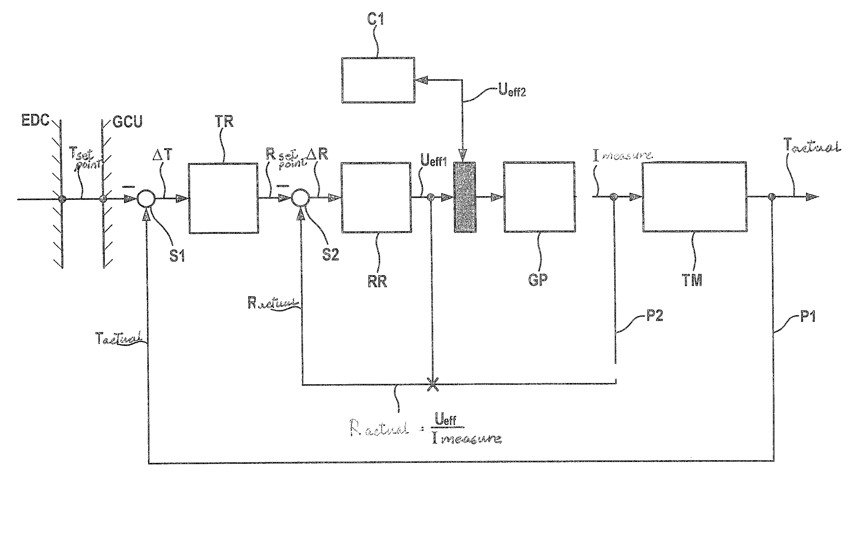
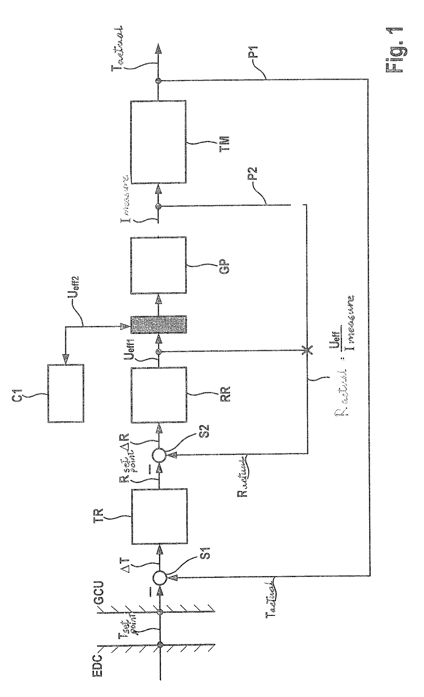
[0029]FIG. 1 shows the design of closed-loop T regulation in combination with an open-loop T control in an exemplary specific embodiment of the present invention. An engine control EDC is connected via an interface to a glow control unit GCU. A closed regulating loop contained in the glow control unit GCU includes a temperature regulator TR, a resistance regulator RR, a sheathed-element glow plug GP and a plug temperature model device TM, which are interconnected in this order. A first connecting loop P1 is provided between the output of plug temperature model device TM and the input of temperature regulator TR.

[0030]A first subtraction circuit S1 into which temperature signals from both connecting lines are entered is connected at the connecting point at the input of temperature regulator TR. More precisely, a setpoint temperature value Tsetpoint sent to glow control unit GCU and an actual temperature value Tactual sent to first connecting loop P1 are applied to first subtraction c...


PUM


Abstract

A method for controlling at least one sheathed-element glow plug in an internal combustion engine, the temperature of the sheathed-element glow plug being controlled as a function of at least one operating parameter of the internal combustion engine in such a way that optimal combustion properties of the internal combustion engine prevail at all times.

Description

BACKGROUND INFORMATION[0001]Sheathed-element glow plugs are usually used to heat up the combustion chambers when an internal combustion engine is started.[0002]A sheathed-element glow plug is an electric heating element in the combustion chamber of an internal combustion engine. The sheathed-element glow plug is heated electrically only briefly at the start. The diesel fuel injected into the combustion chamber during a cold start of a diesel engine usually does not spontaneously ignite as smoothly as described in the theory of the diesel process.[0003]For these reasons, an electrically heatable sheathed-element glow plug is inserted into the combustion chamber and is preheated in the startup phase. This is also known as preheating. The current required for this equals approximately 20 to 40 amperes per cylinder.[0004]However, the diesel fuel injected into the combustion chamber during a cold start of a diesel engine does not usually spontaneously ignite as smoothly as described in t...

Claims


Application Information

Patent Timeline
Patent Type & Authority Patents(United States)
IPC IPC(8): F23Q7/00
CPCF02B77/08F02B77/089F02D41/062F02P19/025F02P19/026F02D41/064F02D2041/1419
Inventor DITTUS, BERNDSCHOLTEN, CARSTENMORITZ, RAINERSCHUMACHER, HERBERTSCHEDLER, THILO
Owner ROBERT BOSCH GMBH
Why Eureka
Try Eureka