Motor

a technology of rare earth magnets and motors, which is applied in the direction of magnetic circuit rotating parts, magnetic circuit shape/form/construction, mechanical energy handling, etc., can solve the problems of lowering the efficiency of the motor, difficult to obtain a high output torque in comparison and difficult to constitute the rotor with sintered rare earth magnets. achieve high mechanical strength, increase mechanical strength, and high degree of accuracy

Inactive Publication Date: 2011-03-15
HITACHI IND EQUIP SYST CO LTD +2
View PDF31 Cites 9 Cited by
  • Summary
  • Abstract
  • Description
  • Claims
  • Application Information

AI Technical Summary

Benefits of technology

[0010]In view of the above-mentioned problems, an object of the present invention is to propose a method which may satisfy desire of enhancing both output torque and efficiency of a motor with the use of rare earth bond magnets.
[0011]According to the present invention, in order to solve the problems stated above, there is provided a permanent magnet rotor of a motor, having a motor rotor core made of a compact formed by compacting a powder material, the compact being composed of a bond magnetic portion mainly formed of a binder and a magnetic powder, and a soft magnetic portion mainly made of a binder and a soft magnetic material, and being formed with the use of a compression molding means, wherein a rotor structure in which the bond magnetic portion has magnetic poles having at least one surface mechanically coupled to the soft magnetic portion. Further, according to the present invention, there is provided a rotor for motor having such a structure that the bond magnetic portion is composed of magnetic segments each being manufactured at a provisional forming step, and being applied with anisotropy during the provisional forming step in order to cause the rotor to have a plurality of magnetic poles obtained from the anisotropy, and being thereafter magnetized by a magnetizing filed during a final forming step. Further, according to the present invention, there is provided a method of forming a rotor, in which during the final forming step, the rotor is formed integrally with a rotor shaft, and accordingly, a rotor product may be manufactured with a high degree of accuracy by a single forming process. The rotor manufactured by this method, has a high mechanical strength, and accordingly, has such a feature that no protecting measure for protecting the outer surface of the rotor with a binding tape or the like, or with a thin metal cylinder made of stainless steel or the like and fitted thereon is required.
[0012]The coreless motor according to the present invention, has an increased mechanical strength so as to eliminate the necessity of a protecting means for protecting the outer surface of the rotor with a binding tape or a thin metal rotor made of stainless steel and fitted thereon, and accordingly, may have a decreased gap, thereby it is possible to expect an increased output power.
[0013]Since substantially no eddy current loss is caused even at a high output power due to the anisotropy of the bond magnets, and accordingly, it is possible to provide a small sized motor having a high degree of efficiency. Further, there may be provided a motor capable of maintaining a coggingless torque property which is inherently owned by a coreless motor. Thus, it is possible to materialize miniaturization of an automobile, an electric appliance and an industrial drive system using the motor, and enhanced efficiency, control ability and enhanced manipulatability of a system product.

Problems solved by technology

However, should sintered rare earth magnets having a large energy product be used, an extra gap in the thicknesswise part of a member for mechanically protecting the magnets would be required in view of the above-mentioned cracking problem.
Further, in the case of a rotor composed of bond magnets (a compact of magnetic powder and resin binder), it is difficult to constitute the rotor with sintered rare earth magnets even though the magnets have large thickness.
With a multiple magnetic pole configuration, a drive frequency of a motor becomes higher, there would be caused a problem of occurrence of eddy currents in magnets, a rotor core and a stator yoke, and a problem of lowering the efficiency of the motor.
In order to solve this problem, it is preferable to use magnets having itself a higher electric resistance, and accordingly, bond magnets are used in order to decrease eddy current, but it is at present difficult to obtain a high output torque in comparison with the sintered rare earth magnets.

Method used


Image

  • Motor
  • Motor
  • Motor

Examples


embodiment 1

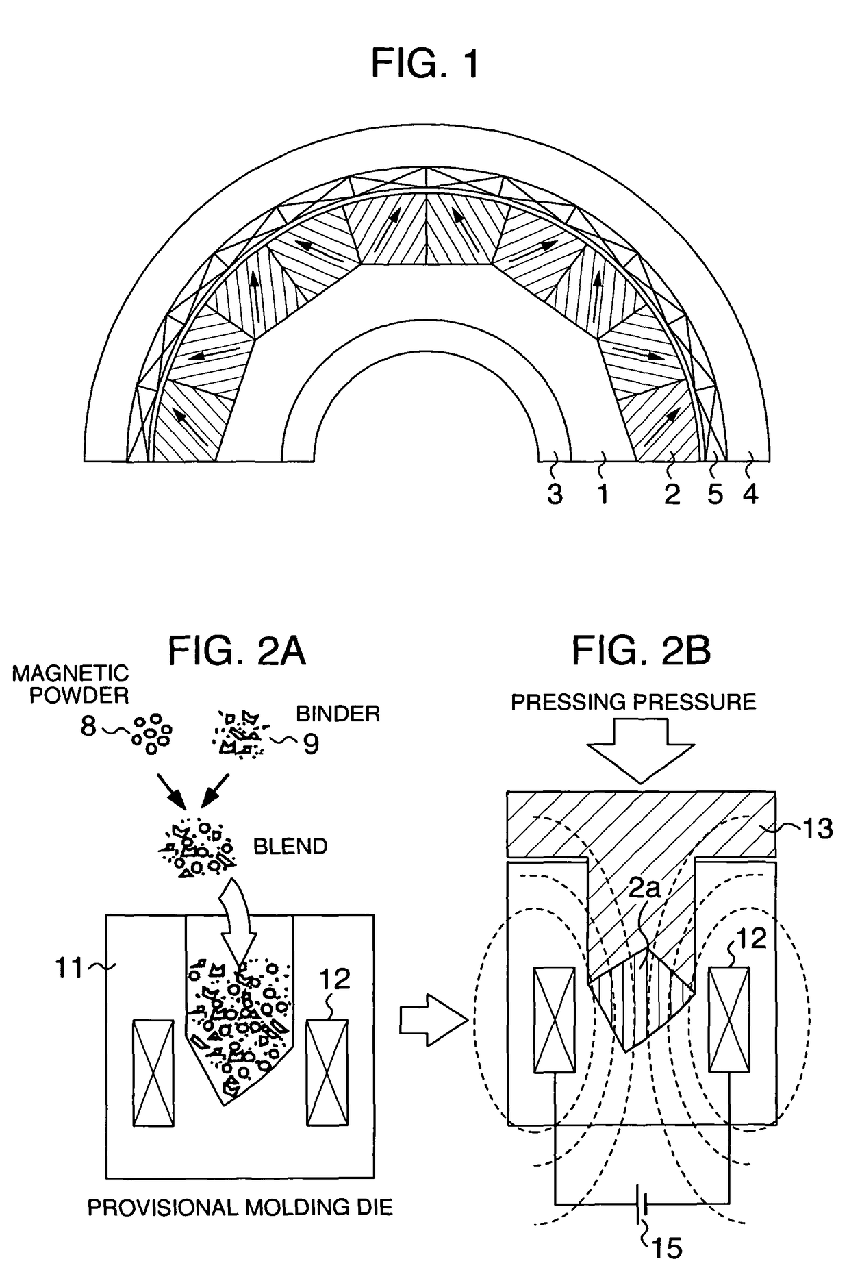
[0025]FIG. 1 is a sectional view illustrating a permanent magnet motor serving as a hollow shaft motor, according to the present invention. In this embodiment, a motor is a three-phase brushless motor composed of a rotor having 10 magnetic poles, and a stator having twelve coils. The stator side has a stator yoke or core 4 formed of a high density SMC, and is composed of a coil compact 5 which is extremely thin in the radial direction. The reason why the SMC is used in this stator is that the motor has multi-magnetic poles, and it is indispensable for decreasing eddy current caused by a rotating magnetic field. On the rotor side, a permanent magnet rotor is characterized by such a structure that a compact is formed by compacting a powder material, the compact being composed of a bond magnetic portion made of a binder and magnetic powder, and a soft magnetic portion made of a binder and soft magnetic powder, characterized in that the bond magnetic portion has magnetic poles having at...

embodiment 2

[0031]Next explanation will be made of a second embodiment. As to the SMC and the magnet of the hollow shaft permanent magnet motor according to the present invention, the higher the molding density and the more excellent the insulation, the higher the property of the hollow shaft permanent magnet motor. It is required to increase the pressure for press molding in order to enhance the molding density. However, should the pressure be excessively high, an insulation film on the magnetic powder surface would be broken, resulting in an increase in eddy current loss. Should the thickness of the insulation film be set to be larger in order to maintain the insulation, lowering of an energy product of a magnet, lowering of magnetic permeability due to insufficient density would be caused, resulting in remarkable lowering of the motor property. In order to simultaneously satisfy these properties contrary to each other, it may be considered to strengthen the film of the magnetic powder.

[0032]...

embodiment 3

[0035]Next, explanation will be made of a system utilizing the hollow shaft motor according to the present invention. FIGS. 9(a) to 9(c) show an example of a system in which technical effects may be expected by using the hollow shaft motor according to the present invention. FIG. 9(a) schematically shows an automobile power steering system. The power steering system comprises a handle 41 and a motor 42. The automobile power steering system has been hydraulically driven, however, since the performance of the motor have been these years enhanced, a power steering system driven by an electric motor becomes available more or less. A motor for driving the steering system is adapted to rotate when the driver manipulates a steering wheel, in order to assist the manipulation, and accordingly, it produces a drive force for changing the direction of wheel tiers. However, in order to remove a heavy load when the motor is rotated due to the operation of the steering wheel by the motor, it is re...


PUM

PropertyMeasurementUnit
thicknessaaaaaaaaaa
diameteraaaaaaaaaa
tensile strengthaaaaaaaaaa

Abstract

It is desired to design a coreless motor in which a gap size is set to be as small as possible, and a magnet having a large energy product is used in order to increase the gap magnetic flux density since the coreless motor has no iron core so that the magnetic flux density is small in the gap part. A rotor core of the motor has a permanent magnet rotor which is formed by a compression molding means, and which is formed of a compact formed by molding a powder material, the compact comprising a bond magnetic portion mainly composed of a binder and a magnetic powder, and a soft magnetic portion mainly composed of a binder and a soft magnetic powder, the bond magnetic portion having magnetic poles having at least one surface which is mechanically bonded to the soft magnetic portion, in order to solve the inherent problems.

Description

BACKGROUND OF THE INVENTION[0001](1) Field of the Invention[0002]The present invention relates to a structure of a motor which materializes an inexpensive permanent magnet motor adapted to be used in the field of industry, electronic appliances or automobiles, and being capable of outputting a high power coggingless toque.[0003](2) Description of Related Art[0004]The so-called motor is used as a drive equipment which converts electric power into mechanical power in the field of industry, electric appliances and automobiles. World-wise demands for energy saving, the provision of motors having a high conversion efficiency are required. However, in addition of the enhancement of the efficiency, miniaturization of motors is also important, and accordingly, for example, magnetic motors utilize magnets each having a high energy product and containing a rare earth material, or a stator core having a higher coil density manufactured by a segmented core process.[0005]However, coreless motors...

Claims


Application Information

Patent Timeline
Patent Type & Authority Patents(United States)
IPC IPC(8): H02K1/27
CPCH02K1/278H02K15/03
Inventor ENOMOTO, YUJIITO, MOTOYAMASAKI, RYOSOOHARA, KOICHIROMITA, MASAHIROKOMURO, MATAHIROMASUZAWA, MASAHIRO
Owner HITACHI IND EQUIP SYST CO LTD
Why Eureka
Try Eureka