Photocatalyst sheet and methods of welding and manufacturing the same

a photocatalyst and welding technology, applied in the direction of catalyst activation/preparation, manufacturing tools, physical/chemical process catalysts, etc., can solve the problems of high cost, complicated process at the welding step, low manufacturing efficiency, etc., and achieve the effect of not raising cost, easy to obtain, and not difficult to process

Inactive Publication Date: 2011-03-22
TAIYO KOGYO CORPORATION
View PDF15 Cites 1 Cited by
  • Summary
  • Abstract
  • Description
  • Claims
  • Application Information

AI Technical Summary

Benefits of technology

[0012]The purpose of the present invention is, considering the problems mentioned above, to offer a photocatalyst sheet and the methods of welding and manufacturing the same, in which the resins and rubbers as substrates or photocatalyst-containing layers are not decomposed by photocatalyst particles, mutual welding of sheets is easy, and the effect of photo-redox reaction of photocatalysts can be readily obtained.
[0020]With a photocatalyst sheet of the present invention, since resin or rubber is exposed on the surface of a photocatalyst-containing layer as the surface of a photocatalyst sheet, either direct thermal adhesion or welding with adhesive or double-stick tape is possible, and no particular process is required for mutual welding of photocatalyst sheets, thereby welding is quite easy. Also, since apatite-coated photocatalyst particles are dispersed and fixed on said photocatalyst-containing layer, the photocatalytic function can be attained. Further, since photocatalyst particles are coated with apatite, the photocatalytic function is not extended to the materials other than the photocatalyst of a photocatalyst-containing layer, the first coated layer of the third aspect, and the substrate. That is, the substrate is hardly decomposed by photo-redox reaction. Especially in the third aspect, by locating the first coated layer made of the same material that in the photocatalyst-containing layer but the photocatalyst removed therefrom between the substrate and the second coated layer as the photocatalyst-containing layer, the photocatalyst-containing layer can be made thin, thereby the amount of apatite-coated photocatalyst particles fixed in the photocatalyst-containing layer can be much reduced. Also, since apatite-coated photocatalyst particles are used as photocatalyst particles, it is not necessary to use such hardly decomposing material as fluorocarbon resin and others. Here, however, apatite-coated photocatalyst particles may be fixed with fluorocarbon resin.
[0023]According to the method of welding the photocatalyst sheets of the present invention, the pre-step treatment as in prior arts to remove the photocatalyst layer of welding breadth, and to expose the resin layer on the surface is no longer necessary, thereby welding is quite easy. Especially in case of thermal adhesion, welding with sufficient welding strength is possible by making the ratio of apatite-coated photocatalyst particles to resin 10-40 weight %.
[0027]According to the method of manufacturing photocatalyst sheets of the present invention, the photocatalyst-containing layer that contains apatite-coated photocatalysts on the outermost layer of the substrate can be easily formed by dispersion coating and other methods.
[0028]With photocatalyst sheets and method of manufacturing the same of the present invention, photocatalyst sheets can be easily obtained and welded mutually. Also, since apatite-coated photocatalyst particles are dispersed and fixed on said photocatalyst-containing layer, a substrate is hardly decomposed by photo-redox reaction caused by the photocatalytic function. Also, since a material capable of mutually welding by melt and solidifying exists on the surface of a photocatalyst-containing layer, pre-step treatment is not required unlike conventional welding process. Especially like the third aspect of the photocatalyst sheets of the present invention, by locating the first coated layer made of the same material that in the photocatalyst-containing layer but the photocatalyst removed therefrom between the substrate and the second coated layer as the photocatalyst-containing layer, the photocatalyst-containing layer can be made thin, thereby the amount of apatite-coated photocatalyst particles fixed in the photocatalyst-containing layer can be much reduced. Also, since apatite-coated photocatalyst particles are used as photocatalyst particles, it is not necessary to use such hardly decomposing material as fluorocarbon resin and others, thereby cost is not raised and process is not difficult. Here also, it is applicable to the case of fixing apatite-coated photocatalyst particles with fluorocarbon resin. Especially, by adopting not only the ultraviolet light responsive type but also the visible light responsive type as photocatalyst particles, the photocatalytic function can be attained by indoor illumination and the like. Also, by making the ratio of apatite-coated photocatalyst particles to resin or rubber 10-90 weight %, the photocatalytic function can be fully attained without deterioration of resin, rubber, or substrates.
[0029]Further, according to the method of welding of photocatalyst sheets of the present invention, in the photocatalyst-containing layer, and also on its surface, apatite-coated photocatalyst particles are preferably dispersed and fixed. Therefore, the resin as its fixer exists on the surface, and photocatalyst-containing layers of photocatalyst sheets are mutually molten and solidified by welding said photocatalyst sheets together with adhesive or double-stick tape, or by thermal treating, and said photocatalyst sheets can thus be welded. Thus, the pre-step of treatment to partially remove the middle layer or the photocatalyst layer upon welding is not necessary unlike prior arts, thereby the welding procedure is largely shortened. Further, in case of thermal adhesion, sufficient welding strength can be attained upon welding of photocatalyst sheets by making the ratio of apatite-coated photocatalyst particles to resin or rubber 10-60 weight %.

Problems solved by technology

However, there may be such a problem that, if the middle layer 13 is located between the second layer 12 and the photocatalyst layer 14, process steps are increased for the manufacture of sheets 10 and 10a, thereby it causes low manufacturing efficiency and high cost.
There may also be a problem that, in case of mutually welding the conventional sheets 10 and 10a, a complicated process at the welding step is required in which the photocatalyst layer of welding breadth must be removed.
There may also be a problem that, in case of fixing photocatalyst particles, such hardly decomposing materials as fluorocarbon and others are necessary to be used, thereby processing is difficult and cost is high.

Method used


Image

  • Photocatalyst sheet and methods of welding and manufacturing the same
  • Photocatalyst sheet and methods of welding and manufacturing the same
  • Photocatalyst sheet and methods of welding and manufacturing the same

Examples


example 1

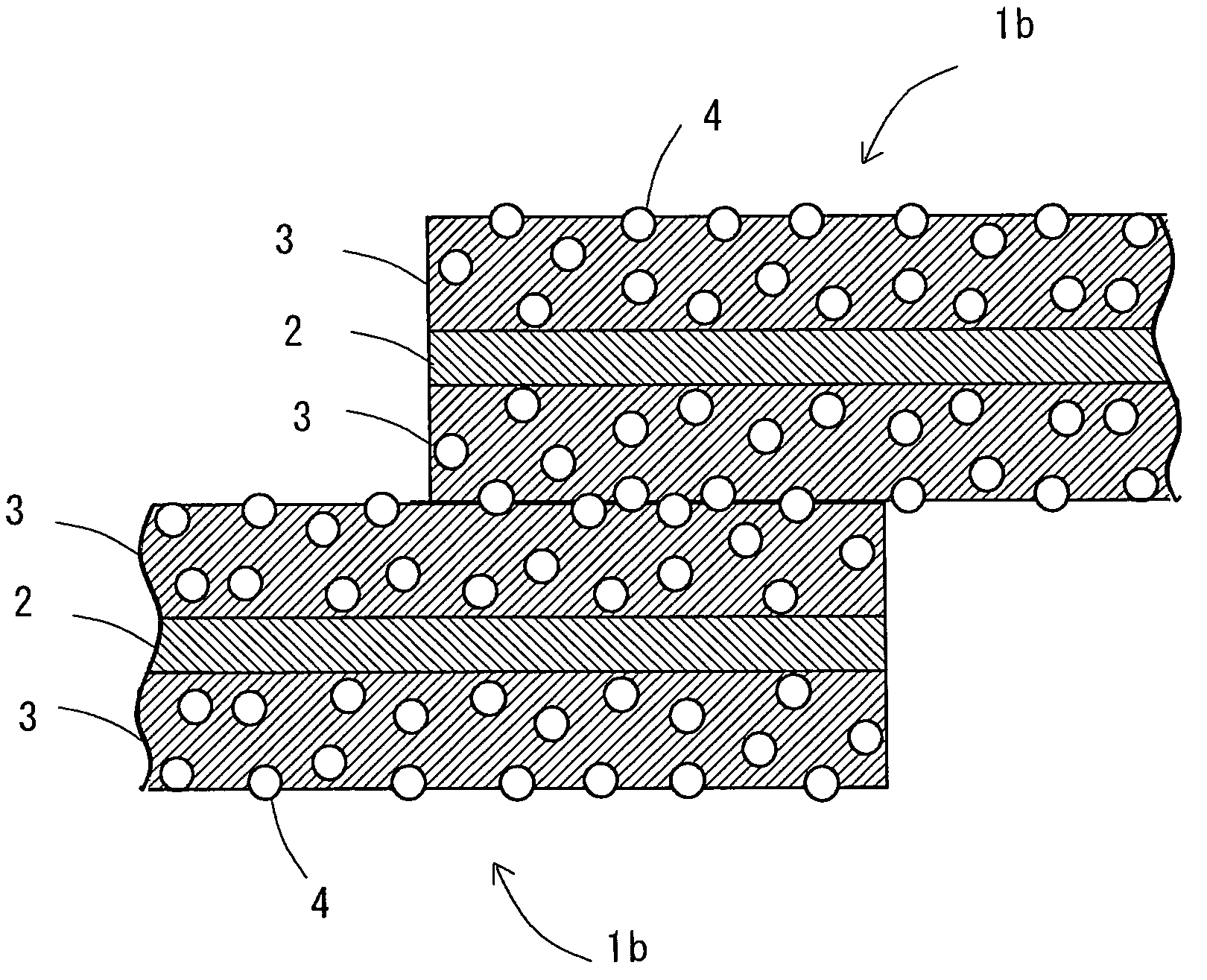
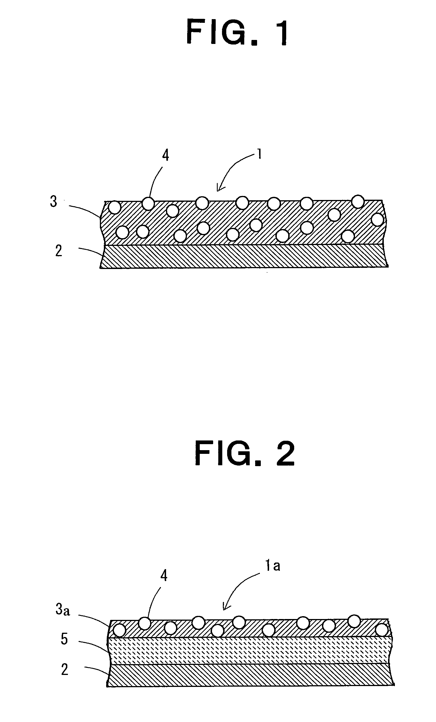
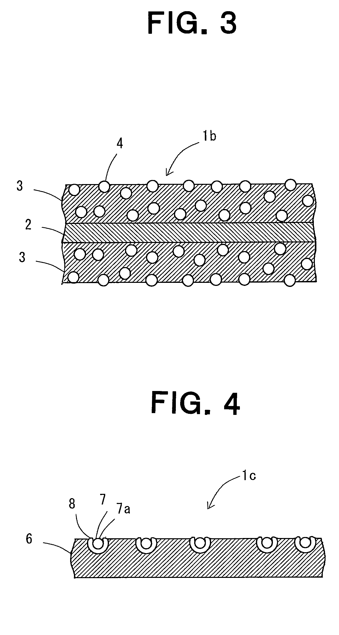
[0073]First, Examples 1-5 and Comparative examples 1-6 are explained for the photocatalyst sheet with the apatite-coated photocatalyst particles fixed on the surface of PVC sheet which is the polyester fiber textile both sides of which are coated with vinyl chloride resin.

[0074]As Example 1, an organic solvent type surface treatment reagent for vinyl chloride resin (Dainichiseika Color & Chemicals Mfg. Co., Ltd., Leatherhit LM-1249, non-volatile component 13.5 weight %) 10.0 g, the powder of apatite-coated anatase type titanium dioxide photocatalyst (Showa Denko, F1S02 (average particle diameter 90 nm, apatite coating 2%)) 0.15 g, and MEK 3.5 g as diluent were mixed and stirred to make Solution A. The ratio of vinyl chloride (PVC) and acrylic (PMA) resins to apatite-coated titanium oxide in said Solution A was 90:10.

[0075]Next, said Solution A was coated by bar coating on one side of PVC sheet that was polyester fiber textile both sides of which were coated with vinyl chloride resin...

example 2

[0076]Similarly to Example 1 except that the powder of apatite-coated titanium dioxide photocatalyst was 0.34 g, Solution B was prepared, and Sample b of Example 2 was prepared. The ratio of vinyl chloride and acrylic resin to apatite-coated titanium dioxide in said Solution B was 80:20.

example 3

[0077]Similarly to Example 1 except that the powder of apatite-coated titanium dioxide photocatalyst was 0.90 g, Solution C was prepared, and Sample c of Example 3 was prepared. The ratio of vinyl chloride resin and acrylic resin to apatite-coated titanium dioxide in said Solution C was 60:40.


PUM

PropertyMeasurementUnit
particle diameteraaaaaaaaaa
forbidden band gap Egaaaaaaaaaa
viscosityaaaaaaaaaa

Abstract

The present invention provides the photocatalyst sheet and the methods of welding and manufacturing the same, by which the substrate and resin of the photocatalyst-containing layer are not decomposed by photocatalyst particles, mutual welding of sheets is easy, and the photo-redox effect of a photocatalyst can be obtained. A photocatalyst sheet (1b) comprises a substrate (2) such as fiber and coated layers (3) on both sides of the substrate (2), and the coated layer (3) constitutes the photocatalyst-containing layer in which apatite-coated photocatalyst particles (4) are dispersed and fixed with resin. Here, the coated photocatalyst particles (4) on the surface of the photocatalyst-containing layer are so fixed as to have the parts exposed from the surface of the photocatalyst-containing layer. In case that photocatalyst sheets (1b) are mutually welded, the photocatalyst-containing layer of each photocatalyst sheet (1b) is not removed, and its surface is mutually held, and welded together by thermal welding or others.

Description

TECHNICAL FIELD[0001]The present invention relates to a photocatalyst sheet, methods of welding and manufacturing the same, in which the resins and rubbers as substrates or photocatalyst-containing layers are not decomposed by photocatalyst particles, and particularly relates to a photocatalyst sheet in which mutual welding of these is easy, and the effect of photo-redox reaction of photocatalysts can be readily obtained.BACKGROUND ART[0002]Photocatalysts are utilized in recent years widely in various fields as they have deodorant, antiseptic, and antifouling functions. For example, when the ultraviolet light included in the sunbeam and others is irradiated on to the sheets containing photocatalyst particles, photo-redox reaction occurs so that the organic fouling or others attached on the surface of the sheet is decomposed. On the other hand, photocatalysts act not only on to fouling substances and others, but also decompose fibers and plastics themselves, so that it is considered ...

Claims


Application Information

Patent Timeline
Patent Type & Authority Patents(United States)
IPC IPC(8): B23B5/16B01J21/06B01J35/00B01J37/02B32B27/12B32B27/18
CPCB01J35/004B01J37/0219B32B27/18B32B27/12B01J21/063Y10T428/2438Y10T428/2991Y10T428/19Y10T428/31826Y10T428/249924Y10T428/3183Y10T428/3154B32B9/00B32B37/04B01J35/02
Inventor TOYODA, HIROSHIABE, KAZUHIRONAKATA, TAKAYUKI
Owner TAIYO KOGYO CORPORATION
Why Eureka
Try Eureka