Gas saving device and method for dissociating water

a technology of gas saving and water, which is applied in the direction of fire-box steam boilers, non-fuel substance addition to fuel, inorganic chemistry, etc., can solve the problems of requiring a substantial amount of energy to achieve, affecting the monitoring public, and slowing down the process

Inactive Publication Date: 2011-03-29
CELIS ROBERTO V
View PDF6 Cites 3 Cited by
  • Summary
  • Abstract
  • Description
  • Claims
  • Application Information

AI Technical Summary

Benefits of technology

[0007]The invention provides for a gas saving device and method for dissociating water into its constituents hydrogen and oxygen gases by utilizing the heat energy of the hot exhaust gases of an engine between temperatures of 710° F. and 950° F. in an efficient method. The method consist of replacing the exhaust pipe directly below the exhaust manifold of the engine with an expanded exhaust pipe that encases the water dissociation device. This dissociation device consist of a long spirally formed superheater tubing preferably stainless steel, with a vast area, that maximizes contact between the superheater tubing and the rapidly passing water. The spirally formed tubing causes the high speed passing water to turbulently move in circular manner, expands and exert great pressure on the inner wall of the superheater tubing to further absorb more heat between 710° F. and 950° F. (Below 710° F. condensation occurs). The high pressure superheated steam, discharges into a large stainless steel cylindrical dissociation chamber, rapidly expands and dissociates into its constituent hydrogen and oxygen gases. The hydrogen and oxygen gases so produced are immediately drawn into the combustion chamber through the intake manifold of the engine to burn and causes efficient combustion of the fuel that results in fuel savings, add power and speed to the engine, reduces emission, cools the engine, reduces engine wear, and releases oxygen to make the environment more healthful.
[0008]When the engine stops, the spring-loaded valve automatically closes and prevents flooding.

Problems solved by technology

Although hydrogen is a clean and a powerful source of energy, it is a chemically active element and not available in the free state in nature in elemental gaseous form, it must be produced and stored for utilization in engines, but hazardous to the monitoring public when carried on board a vehicle in case of accident.
Hydrogen can be obtained from compounds by breaking chemical bonds but requires a substantial amount of energy to accomplish.
From water, hydrogen is produced by electrolysis but it is slow a process and insufficient to power a vehicle when carried on board.
All the above processes require storage of hydrogen to be carried on board to be used as fuel for motor vehicles and would create great danger to the motoring public.

Method used


Image

  • Gas saving device and method for dissociating water
  • Gas saving device and method for dissociating water
  • Gas saving device and method for dissociating water

Examples


Embodiment Construction

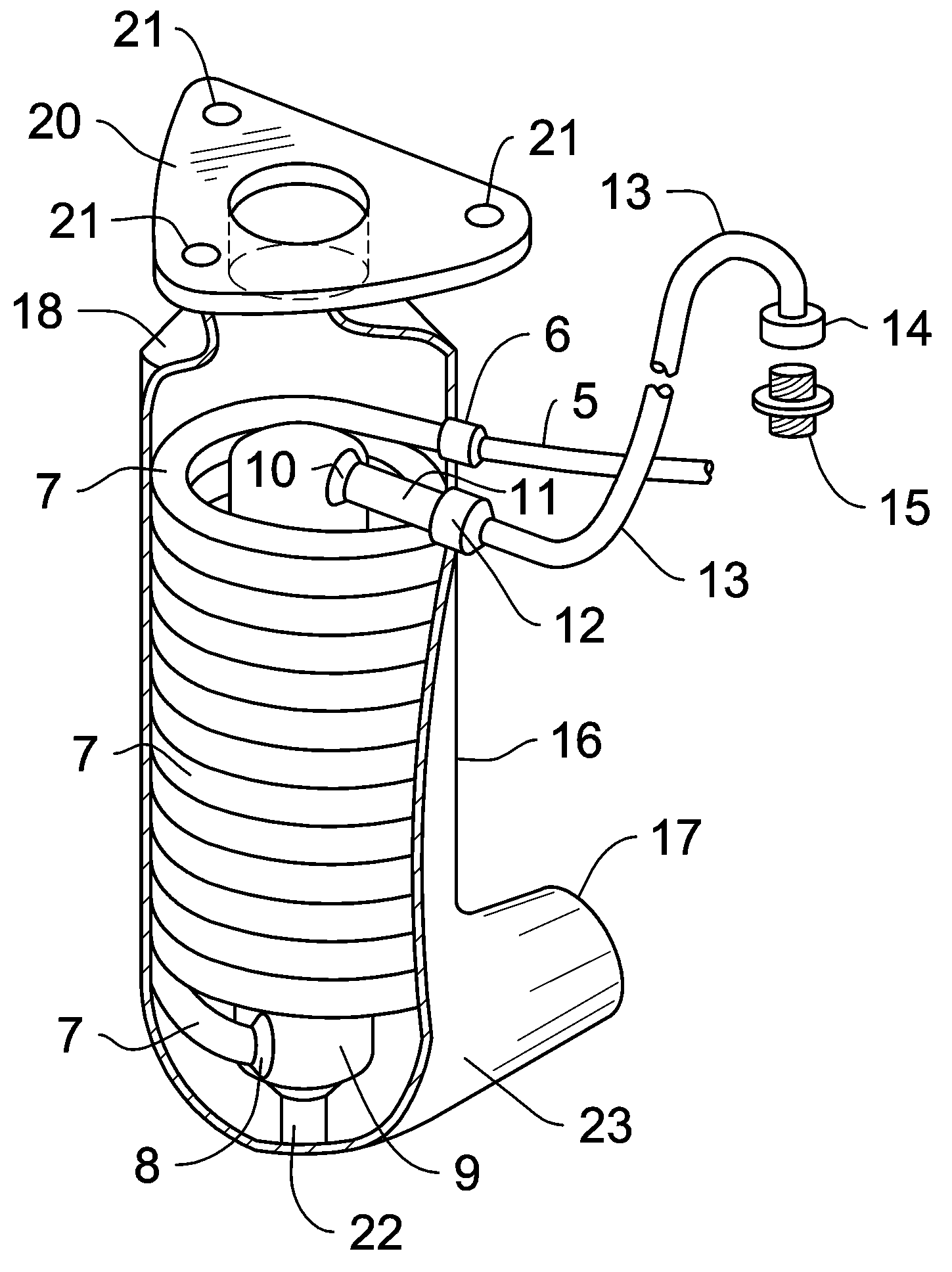
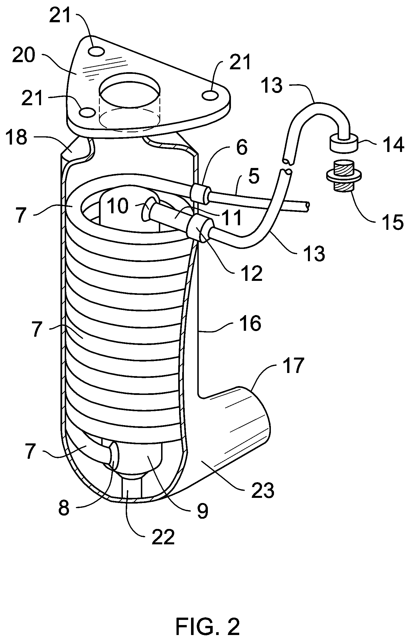
[0009]With reference to FIG. 2 of the isometric partially cut-away view of the water dissociation device, is seen to include an expanded exhaust pipe 16 adapted to be connected to the exhaust manifold of an engine, a spiral superheater tubing 7, encased inside said expanded exhaust pipe, said exhaust pipe having an exhaust gas inlet 20, and an external gas outlet 17 at the opposing end, to allow the hot exhaust gas from the engine to pass through and heat the spiral superheater tubing between 710° F. and 950° F.; said spiral superheater tubing having water supply inlet 6 to one end thereof, a dissociation chamber 9 is provided inside said expanded exhaust pipe and connected to the opposing end of said spiral superheater tubing at 8, said dissociation chamber having an outlet that discharges the dissociated hydrogen and oxygen gases into the intake manifold through outlet 10. Outlet pipe 11 is connected and in fluid communication with conduit 13, at outlet coupling 12, through intake...


PUM


Abstract

The method consists of replacing the exhaust pipe directly below the exhaust manifold of an engine with an expanded exhaust pipe that encases the water dissociation device (9), consisting of a long, spirally formed super heater, preferably stainless steel tubing (7) to have vast area of contact to maximize heat transfer to the passing water. The spirally formed tubing causes the passing water to turbulently move in circular manner, superheat, exert great pressure on the inner wall of the superheater tubing, discharges and expands in the large dissociation chamber (9) into its constituents hydrogen and oxygen gases that are immediately sucked into the combustion chamber of the engine to cause efficient combustion of the fuel, reduce emission, add power and speed, increase mileage and release oxygen.

Description

CROSS-REFERENCE TO RELATED APPLICATIONS[0001]This application is an U.S. national phase application under 35 U.S.C. §371 based upon co-pending International Application No. PCT / PH2006 / 000016 filed on Jul. 11, 2006. Additionally, this U.S. national phase application claims the benefit of priority of co-pending International Application No. PCT / PH2006 / 000016 filed on Jul. 11, 2006 and Philippines Application No. 1-2005-000344 filed on Jul. 12, 2005. The entire disclosures of the prior applications are incorporated herein by reference. The international application was published on Jan. 18, 2007 under Publication No. WO 2007 / 008091.TECHNICAL FIELD[0002]The present invention relates to a gas saving method and device and more particularly to a method for converting water into fuel enhancer for combustion engines by dissociating water into its constituent hydrogen and oxygen gases by efficiently utilizing the hot exhaust gases of the engine for heating the dissociation device. The hydroge...

Claims


Application Information

Patent Timeline
Patent Type & Authority Patents(United States)
IPC IPC(8): F02B43/08
CPCC01B3/042C01B13/0207B01J2219/185B01J2219/1944Y02E60/364Y02E60/366Y02E60/36Y10S123/12
Inventor CELIS, ROBERTO V.
Owner CELIS ROBERTO V
Why Eureka
Try Eureka