
Liquid crystal compound having negative dielectric anisotropy, liquid crystal composition, and liquid crystal display device

a technology of dielectric anisotropy and liquid crystal compound, which is applied in the direction of liquid crystal composition, organic chemistry, chemistry apparatus and processes, etc., can solve the problems of compound not being sufficient in some cases to reduce the driving voltage of the liquid crystal display device, and the liquid crystal compound has not yet been found to satisfy the requirements

Inactive Publication Date: 2011-03-29
JNC PETROCHEM CORP +1
View PDF14 Cites 8 Cited by
  • Summary
  • Abstract
  • Description
  • Claims
  • Application Information

AI Technical Summary

Benefits of technology

[0098]According to the invention, such a liquid crystal compound is provided that not only has a negatively large dielectric anisotropy (Δ∈), but also has at least one of characteristics including a stability to heat, light and so forth, a high clear point, a suitable refractive index anisotropy (Δn) and a good compatibility with other liquid crystal compounds. According to the invention, such a liquid crystal composition is provided that has a low viscosity, a suitable refractive index anisotropy (Δn), a suitable negative dielectric anisotropy (Δ∈) and a low threshold voltage, and also has at least one of characteristics including a high maximum temperature of a nematic phase and a low minimum temperature of a nematic phase. According to the invention, such a liquid crystal display device is provided that has at least one of characteristics including a short response time, a small electric power consumption, a small driving voltage and a large contrast, and capability of being used in a wide temperature range.

Problems solved by technology

However, such a liquid crystal compound has not yet been found that satisfies all of characteristics (1) to (6) by a sole compound.
However, the compound (a) has a negative dielectric anisotropy (Δ∈), but the extent thereof is not necessarily large in some cases, and therefore, the compound is not sufficient in some cases for decreasing the driving voltage of a liquid crystal display device of the VA mode and the IPS mode.

Method used


Image

  • Liquid crystal compound having negative dielectric anisotropy, liquid crystal composition, and liquid crystal display device
  • Liquid crystal compound having negative dielectric anisotropy, liquid crystal composition, and liquid crystal display device
  • Liquid crystal compound having negative dielectric anisotropy, liquid crystal composition, and liquid crystal display device

Examples


example 1

Synthesis of 5-[4-(4-ethoxy-2,3-difluorophenoxymethyl)-cyclohexyl]-2-propyltetrahydropyran (Compound No. 9)

[0218]

First Step

[0219]In a reactor under nitrogen atmosphere, 200 mL of THF was added to 41.2 g of methyltriphenylphosphonium bromide, and the mixture was cooled to −20° C., to which 12.9 g of t-BuOK was added, followed by stirring for 1 hour. A solution containing 15.0 g of 1.4-dioxaspiro[4.5]decan-8-one dissolved in 200 mL of THF was added dropwise thereto, followed by stirring at −20° C. for 1 hour. The temperature of the reaction mixture was increased to room temperature, and 200 mL of water was added to the reaction mixture, followed by extracting three times with 300 mL of toluene. The resulting organic layer was washed with water, dried over anhydrous magnesium sulfate, and the solvent was concentrated to about 200 mL under reduced pressure, and the concentrated solution was placed in 1,000 mL of hexane, followed by removing deposited solid matters. The solvent was disti...

example 2

Synthesis of 5-[4-(4-ethoxy-2,3-difluorophenoxymethyl)-cyclohexyl]-2-pentyltetrahydropyran (Compound No. 11)

[0236]

[0237]The same synthesis procedures as in Example 1 were carried out except that n-pentyllithim was used instead of n-propyllithium used in thirteenth step to synthesize 5-[4-(4-ethoxy-2,3-difluorophenoxymethyl)cyclohexyl]2-pentyltetrahydropyran.

[0238]The chemical shifts δ (ppm) in 1H-NMR analysis were as follows, and thus the resulting compound was identified as 5-[4-(4-ethoxy-2,3-difluorophenoxymethyl)cyclohexyl]2-pentyltetrahydropyran (Compound No. 11). The solvent for measurement was CDCl3.

[0239]Chemical shift δ (ppm): 6.60 (m, 2H), 4.05 (q, 2H), 4.00 (m, 1H), 3.75 (d, 2H), 3.14 (m, 1H), 3.13 (t, 2H), 2.0-1.6 (m, 6H), 1.6-1.1 (m, 14H), 1.1-1.0 (m, 5H), 0.91 (t, 3H)

[0240]The resulting compound No. 11 had phase transition temperatures (° C.) of C 47.3 N 126.2 Iso.

example 3

Synthesis of 5-[4-(4-ethoxy-2,3-difluorophenoxymethyl)cyclohexyl]-2-vinyltetrahydropyran (Compound No. 12)

[0241]

First Step

[0242]2.55 g of trimethylsilylacetylene was dissolved in 20 mL THF, and then 15.7 mL of a 1.66 M hexane solution of n-butyllithium was added dropwise thereto at −70° C., followed by stirring at that temperature for 1 hour. To the resulting solution, a solution containing 9.12 g of 5-[4-(4-ethoxy-2,3-difluorophenoxymethyl)cyclohexyl]tetrahydropyran-2-one obtained in the twelfth step of Example 1 dissolved in 30 mL of THF was added dropwise at −70° C., followed by stirring at that temperature for 1 hour, and then the temperature of the solution was gradually increased to room temperature. The reaction product was poured into 50 mL of a saturated ammonium chloride aqueous solution, and the mixture was extracted with diethyl ether. The organic layer was washed with water and concentrated under reduced pressure. The resulting brown residue was purified by silica gel c...


PUM

PropertyMeasurementUnit
temperatureaaaaaaaaaa
thicknessaaaaaaaaaa

Abstract

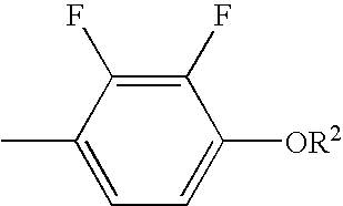
A liquid crystal compound is provided that has excellent characteristics, such as a negatively large dielectric anisotropy. A liquid crystal composition containing the compound, and a liquid crystal display device containing the composition are also provided. A compound having the three factors, i.e., (1) a tetrahydropyran ring, (2) —CH2O— or —OCH2— and (3)exhibits excellent characteristics including a negatively large dielectric anisotropy. The use of the compound having the characteristics provides an excellent liquid crystal composition and an excellent liquid crystal display device.

Description

CROSS-REFERENCE TO RELATED APPLICATION[0001]This application claims the priority benefit of Japan application serial no. JP2008-123171, filed May 9, 2008. The entirety of the above-mentioned patent application is hereby incorporated by reference herein and made a part of specification.BACKGROUND OF THE INVENTION[0002]1. Field of the Invention[0003]The present invention relates to a novel liquid crystal compound and a liquid crystal composition. More specifically, it relates to a liquid crystal compound having a negative dielectric anisotropy (Δ∈), a liquid crystal composition containing the compound, and a liquid crystal display device containing the liquid crystal composition.[0004]2. Related Art[0005]A liquid crystal display device is classified, depending on the display mode thereof, into such modes as DS (dynamic scattering), TN (twisted nematic), GH (guest host), STN (super twisted nematic), IPS (in-plane switching), VA (vertical alignment) and OCB (optically compensated bend)....

Claims


Application Information

Patent Timeline
Patent Type & Authority Patents(United States)
IPC IPC(8): C09K19/34C09K19/30C07D309/02C07D309/06C07D309/10
CPCC07D309/06C07D309/10C09K19/3402C09K2019/0407C09K2019/3422C09K2323/00
Inventor MASUKAWA, TOKIFUMI
Owner JNC PETROCHEM CORP
Learn More