RF mixer with inductive degeneration

a technology of inductive degeneration and mixer, which is applied in the field of analog circuits, can solve the problems of nonlinear relationship between the input current isub>q1 /sub>and the input current isub>rf /sub>, and the output signal produces unacceptable levels of intermodulation distortion, and a separate notch or band stop filter is needed, so as to achieve further noise reduction, the effect of extending the dynamic range and reducing nois

Inactive Publication Date: 2011-03-29
ANALOG DEVICES INC
View PDF19 Cites 8 Cited by
  • Summary
  • Abstract
  • Description
  • Claims
  • Application Information

AI Technical Summary

Benefits of technology

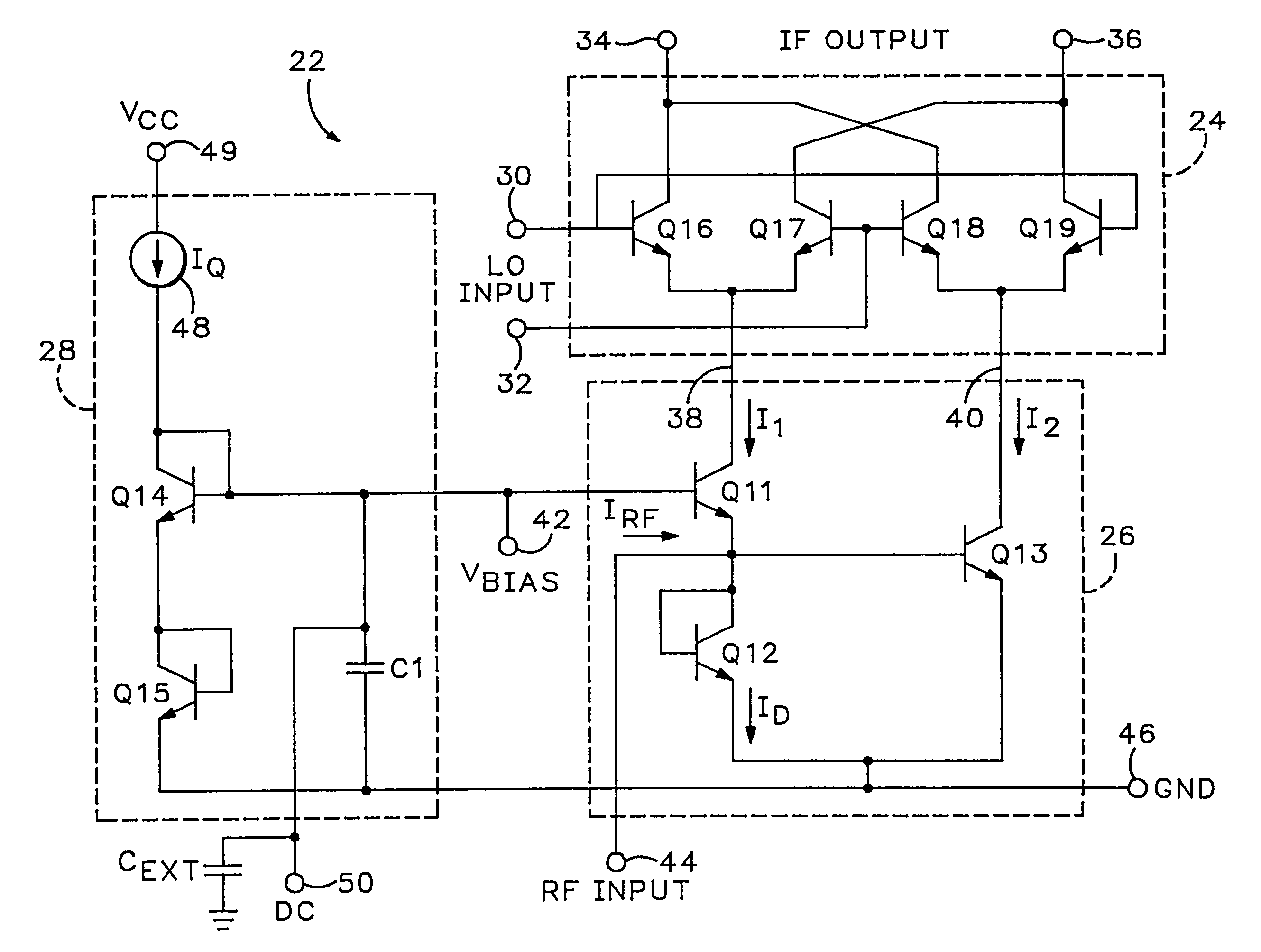
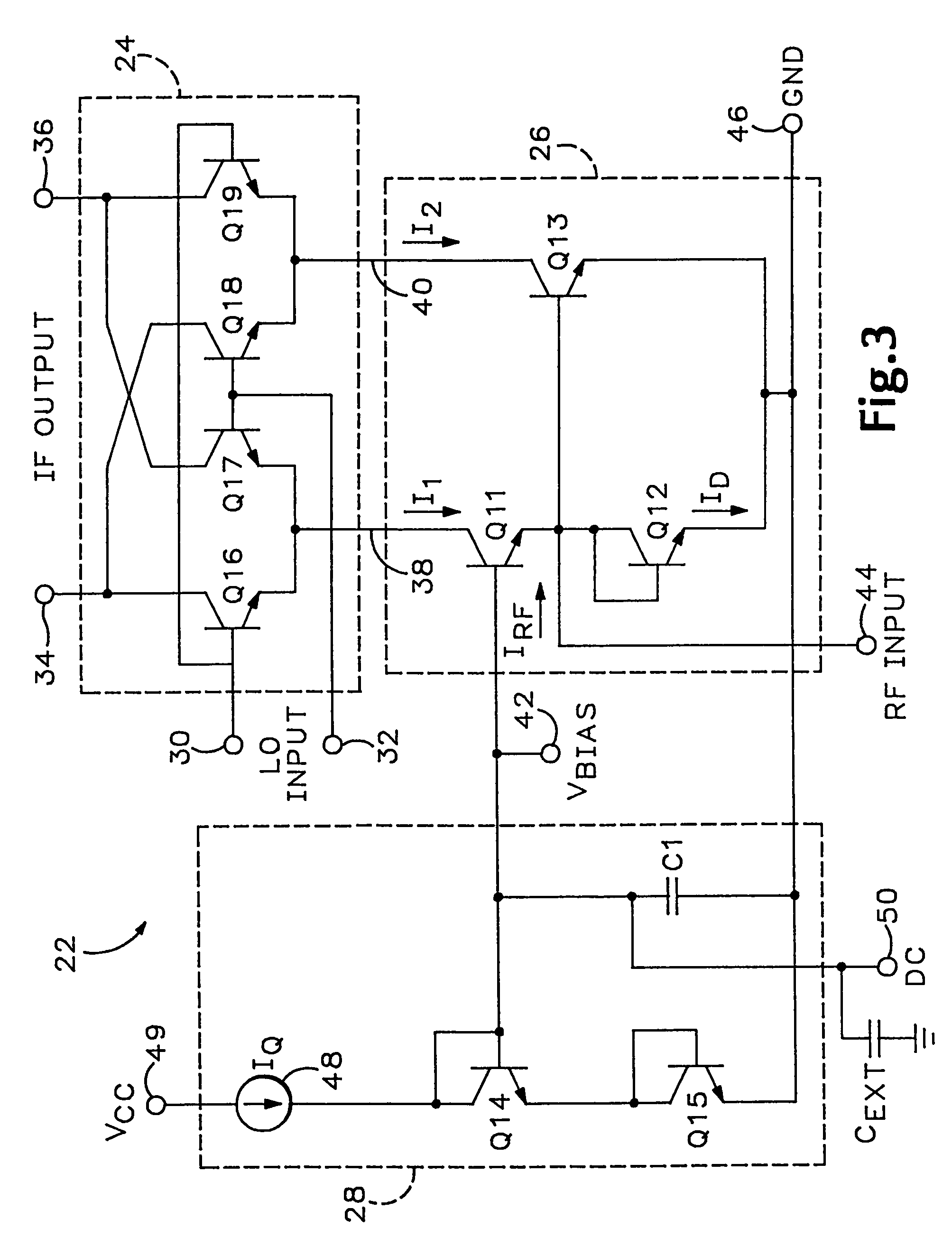
[0010]To achieve these and other objects, an RF mixer constructed in accordance with the present invention provides extended dynamic range with reduced noise by utilizing degeneration inductors in the RF input section of a doubly balanced mixer. Degeneration inductors are also utilized in a mixer having a class AB input section. A current mirror in the class AB input section is also inductively degenerated for further noise reduction. The input section is biased by an all-NPN bandgap reference cell which is tightly integrated into the input section so as to reduce the power supply voltage required for the reference cell. The mixer can be optimized for wide input voltage ranges or low distortion.
[0011]One aspect of the present invention is an RF mixer comprising: a mixer core having an LO port for receiving an LO signal, an IF port for providing an IF output signal, and an input port having an input terminal for receiving a current signal; and an RF input section coupled to the input terminal for providing the current signal responsive to an RF input signal; wherein the RF input section includes: a transistor coupled to the input terminal, and an inductor coupled to the transistor to extend the dynamic range of the mixer.
[0012]Another aspect of the present invention is an RF mixer comprising: a mixer core having a first input terminal for receiving a first current signal and a second input terminal for receiving a second current signal; a first subcell coupled to the first input terminal of the mixer core to provide the first current signal to the mixer core responsive to an RF input signal, the first subcell having a first transistor and a first inductor coupled to the first transistor to extend the dynamic range of the mixer, and a second subcell coupled to the second input terminal of the mixer core to provide a second current signal to the mixer core responsive to an RF input signal, the second subcell having a second transistor and a second inductor coupled to the first transistor to extend the dynamic range of the mixer.
[0013]A further aspect of the present invention is a current mirror comprising: a first transistor having a first terminal for receiving an input signal, a second terminal coupled to the first terminal of the first transistor to cause the first transistor to operate as a diode, and a third terminal; a first inductor coupled between the third terminal of the first transistor and a common node to reduce the noise of the current mirror; a second transistor having a first terminal for transmitting an output signal, a second terminal coupled to the first terminal of the first transistor, and a third terminal; and a second inductor coupled between the third terminal of the second transistor and a common node to reduce the noise of the current mirror.

Problems solved by technology

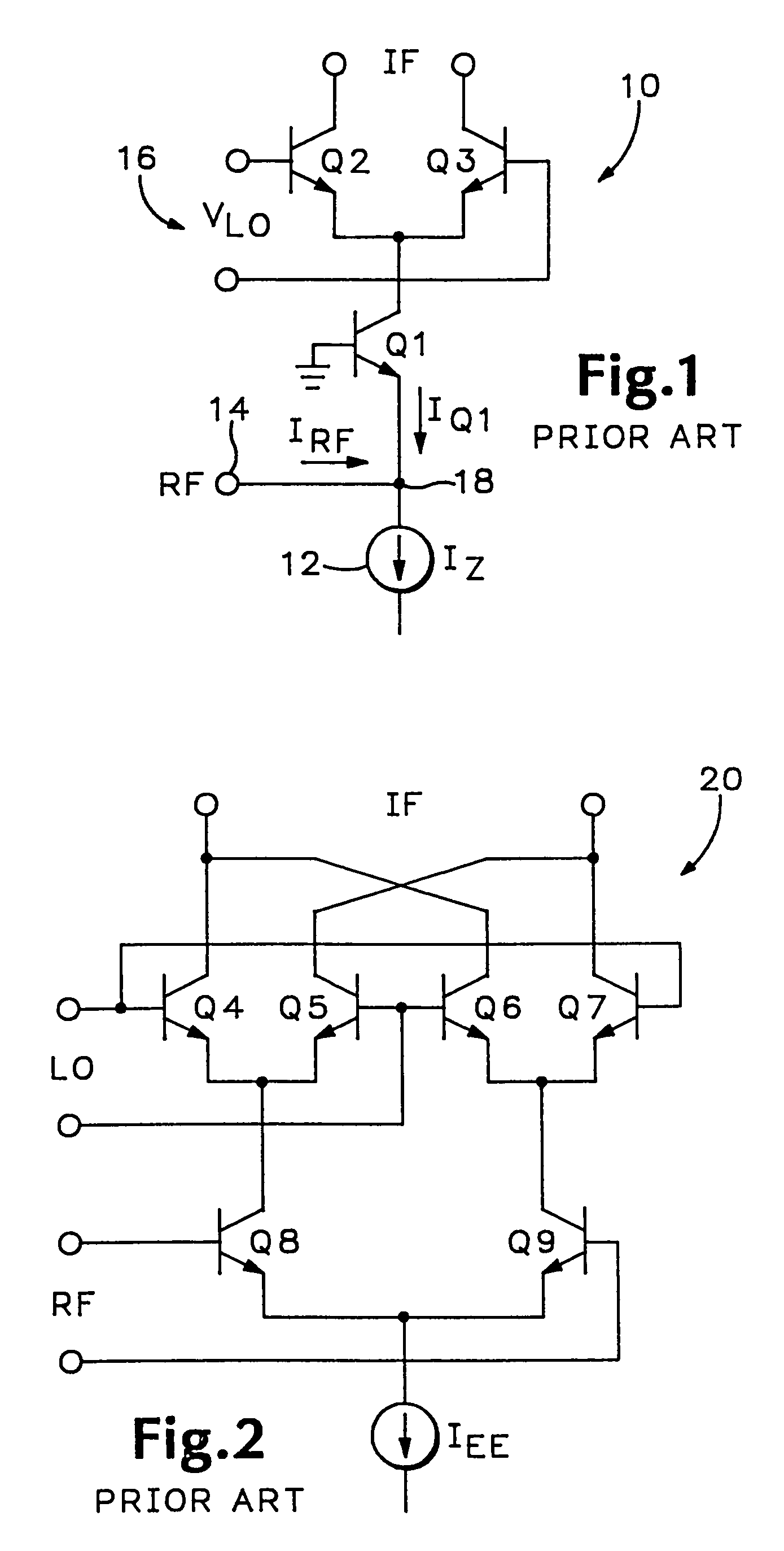
Unfortunately, the relationship between the current IQ1 and the input current IRF is nonlinear.
This nonlinearity, which is predominently even-order, of the common-base transistor Q1 produces unacceptable levels of intermodulation distortion in the IF output signal.
Another problem with the singly-balanced mixer is that a separate notch or band stop filter is needed to remove the local oscillator component from the IF signal.
Although the Gilbert mixer does cancel the local oscillator component in the IF output signal, it does little to improve the basically-nonlinear performance of the singly-balanced mixer 10 of FIG. 1.
It also has a limited dynamic range due to nonlinearities, which are now largely odd-order in nature.

Method used


Image

  • RF mixer with inductive degeneration
  • RF mixer with inductive degeneration
  • RF mixer with inductive degeneration

Examples


second embodiment

[0054]Referring now to FIG. 4, the biasing circuit 28 is shown. This embodiment includes a proportional to absolute temperature (PTAT) cell, shown generally at 52, an operational amplifier 54, and a filter shown generally at 56. The PTAT cell 52 includes transistors Q20 and Q21 along with resistors R1, R2 and RBIAS. The emitter areas of transistors Q20 and Q21 have a predetermined relationship. As shown in FIG. 4, the emitter area (Me) of transistor Q21 is M times the emitter area (e) of transistor Q20. It can readily be shown that this ratio produces a current (IQ21) through the resistor RBIAS given by the following expression:

IQ21=(VT / RBIAS)×lnM

where VT is the thermal voltage (kT / q), which is approximately equal to 26 mV at 300° K. This current IQ21 is thus proportional-to-absolute-temperature (PTAT).

[0055]The bases of transistors Q20 and Q21 are coupled to the RF input 44 via the filter 56. The filter 56, comprised of resistor R3 and capacitor CF, removes the RF signal and passes...

third embodiment

[0056]the biasing circuit, shown in FIG. 5, adds two additional diodes D1 and D2 to the biasing circuit of FIG. 4. By using the diodes D1 and D2, the biasing circuit 28 can be decoupled from the RF input 44. Thus, the filter (resistor R3 and capacitor CF) of FIG. 4 is no longer required. The biasing circuit of FIG. 5 operates in substantially the same manner as the biasing circuit of FIG. 4, except that the voltage at the bases of transistors Q20 and Q21 is established by the voltage across diode D2 and not directly by the voltage across diode-connected transistor Q12 of the RF input section 26.

[0057]Alternatively, two resistors can be used in place of the two diodes D1 and D2 to establish the voltage at the bases of transistors Q20 and Q21. However, the diodes allow a lower current to be used to establish a low operating impedance at the bases of Q20, Q21.

[0058]Referring now to FIG. 6, another embodiment of the biasing circuit 28 is shown. This embodiment uses a PTAT current instea...


PUM


Abstract

An RF mixer provides extended dynamic range with reduced noise by utilizing degeneration inductors in the RF input section of a doubly balanced mixer. Degeneration inductors are also utilized in a mixer having a class AB input section. A current mirror in the class AB input section is also inductively degenerated for further noise reduction. The input section is biased by an all-NPN bandgap reference cell which is tightly integrated into the input section so as to reduce the power supply voltage required for the reference cell. The mixer can be optimized for wide input voltage ranges or low distortion.

Description

[0001]This application is a divisional of U.S. application Ser. No. 08 / 918,728 filed Aug. 21, 1997 now U.S. Pat. No. 6,122,497 which is herein incorporated by reference.FIELD OF THE INVENTION [0002]This invention relates generally to analog circuits and more particularly to radio frequency (RF) mixers. This application discloses various improvements to the subject matter disclosed in co-pending U.S. patent application Ser. No. 08 / 377,752 which has a common assignee with the present invention, and which is herein incorporated by reference.DESCRIPTION OF THE RELATED ART[0003]A simple mixer is shown in FIG. 1. This prior art mixer is known as a singly-balanced mixer. The singly-balanced mixer 10 includes a differential pair of transistors (Q2, Q3) and a common-base transistor (Q1) connected to the emitters thereof. A constant current source 12 is connected in series with common-base transistor Q1 to provide a quiescent current to the mixer 10. This quiescent current (IZ) is the current...

Claims


Application Information

Patent Timeline
Patent Type & Authority Patents(United States)
IPC IPC(8): H04B1/28H03D7/14
CPCH03D7/1425H03D7/1433H03D7/1408H03D7/1441H03D7/145H03D7/1458H03D7/1491H03D2200/0033H03D2200/0043
Inventor GILBERT, BARRIE
Owner ANALOG DEVICES INC
Why Eureka
Try Eureka