
Method and system for laser treatment of refractive errors using offset imaging

a laser treatment and offset imaging technology, applied in laser surgery, medical science, therapy, etc., can solve the problems of reducing predictability, lack of precision for a given, and the nature of the boundary between the optical zone and the untreated area of the laser surgery technique to achieve hyperopic refractive error correction. , to achieve the effect of large area coverage and convenient design

Inactive Publication Date: 2011-04-05
AMO MFG USA INC
View PDF53 Cites 0 Cited by
  • Summary
  • Abstract
  • Description
  • Claims
  • Application Information

AI Technical Summary

Benefits of technology

[0012]The invention comprises a method and system for performing ablative photodecomposition of the corneal surface which is capable of providing relatively smooth transition zones along with accurate sculpting of the anterior or other corneal surface to effect symmetric or asymmetric refractive corrections requiring relatively large area coverage. The invention is further capable of smoothing the corneal surface after a refractive correction has been ablated, and is further effective in performing phototherapeutic keratectomies. The invention uses a laser beam of smaller beam size than known devices, and can be readily designed into new ophthalmological surgery systems or retrofitted in existing ophthalmological surgery systems.
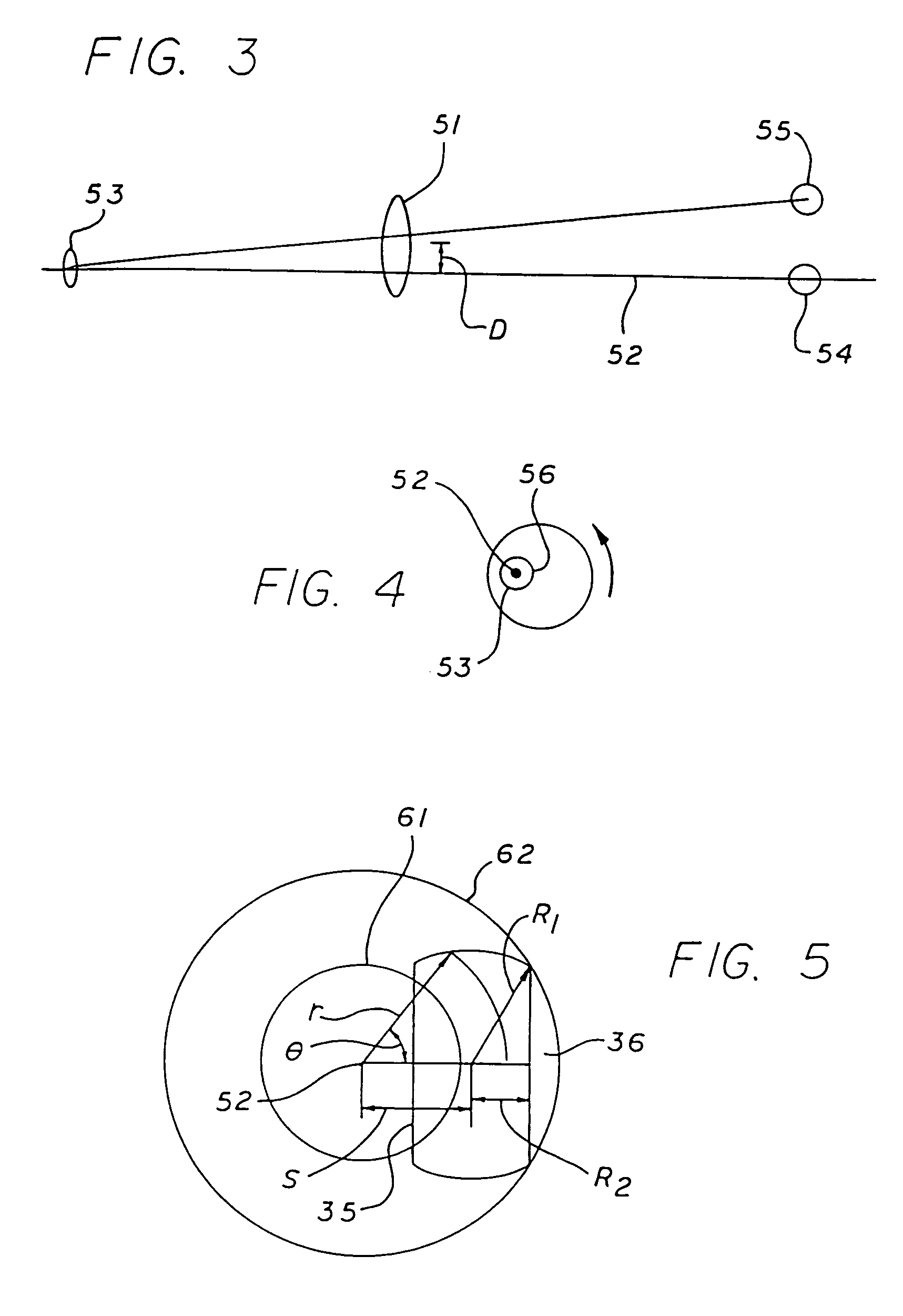
[0020]The system and method can be incorporated into existing laser surgery systems having a variable diameter iris aperture and a variable width slit mounted on a rotatable platform by modifying the mounting mechanism used for the existing imaging lens to enable the lens to be translated radially of an axis of rotation and rotated with the slit platform about the axis of rotation. The invention is capable of providing wider area beam coverage of the corneal surface with a laser having a conventional beam size, thereby eliminating any need for a larger beam laser and providing wider area coverage with lower energy requirements than many known devices.

Problems solved by technology

One of the major difficulties encountered in the application of laser surgery techniques to effect hyperopic refractive error corrections lies in the nature of the boundary between the optical zone and the untreated area.
This natural phenomenon, sometimes termed the “hyperopic shift” in phototherapeutic keratectomy, causes a lack of precision for a given surgical procedure and diminished predictability, which tend to counteract the beneficial effects of the refractive correction procedure and thereby reduce the desirability of the procedure to the prospective patient.
While somewhat effective, these efforts suffer from the disadvantage of typically requiring additional optical elements (such as a rotatable off-axis mirror or revolving prism having suitable optical properties) which adds complexity to the delivery system optics commonly found in laser sculpting ophthalmological surgical systems.
This technique, while considered effective for some purposes, requires a relatively complicated optical delivery system in order to provide the desired profiling.
In addition, the use of mirrors and prisms in delivery system optics in laser surgery systems suffers from certain disadvantages.
In particular, the addition of prisms decreases the total energy transmission of the system.
Another difficulty encountered in the application of laser surgery techniques to effect hyperopic refractive error corrections lies in the requirement for relatively large transition zones outside the optical zone.
In general, the larger the beam diameter the less uniform the energy density across the beam and the less reliable the photoablation process.
Further, the increased beam area requires a laser beam of substantially greater energy, which necessitates a more expensive laser.
Also, the increased energy flowing through the optical components causes optical deterioration at a faster rate, thereby increasing maintenance and replacement costs.
Another disadvantage inherent in a rotating mask system is that the resulting ablation frequently exhibits a central ablation surface which is rougher than desired when a hyperopic correction is conducted.

Method used


Image

  • Method and system for laser treatment of refractive errors using offset imaging
  • Method and system for laser treatment of refractive errors using offset imaging
  • Method and system for laser treatment of refractive errors using offset imaging

Examples


Embodiment Construction

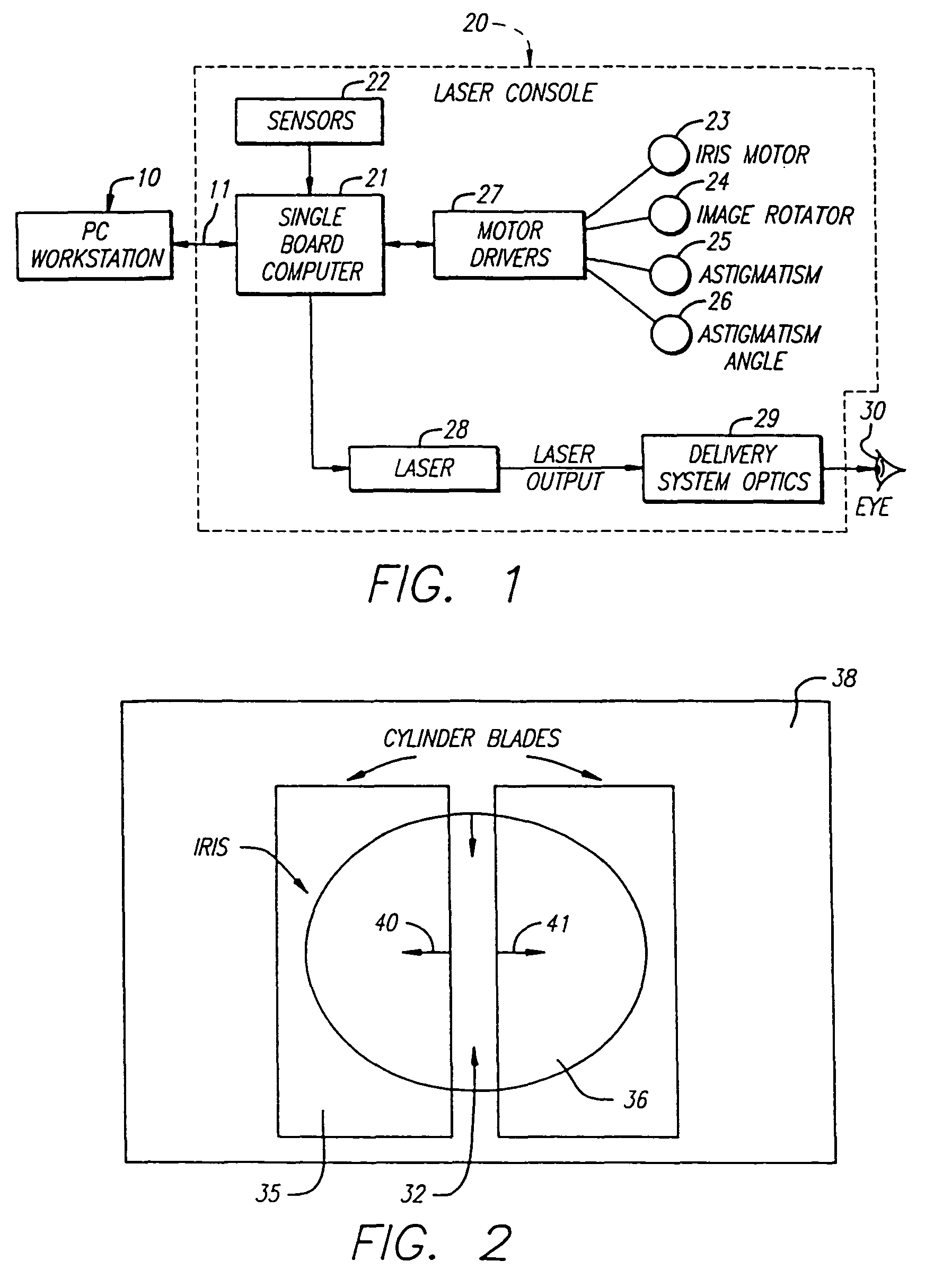
[0030]Turning now to the drawings, FIG. 1 illustrates a block diagram of an ophthalmological surgery system for incorporating the invention. As seen in this Fig., a personal computer (PC) work station 10 is coupled to a single board computer 21 of a laser surgery unit 20 by means of a first bus connection 11. PC work station 10 and the subcomponents of laser surgery unit 20 are known components and preferably comprise the elements of the VISX TWENTY / TWENTY EXCIMER LASER SYSTEM available from Visx, Incorporated of Santa Clara, Calif. Thus, the laser surgery system 20 includes a plurality of sensors generally designated with reference numeral 22 which produce feedback signals from the movable mechanical and optical components in the laser optical system, such as the elements driven by an iris motor 23, an image rotator 24, an astigmatism motor 25 and an astigmatism angle motor 26. The feedback signals from sensors 22 are provided via appropriate signal conductors to the single board c...


PUM


Abstract

An ophthalmological surgery system and method for performing ablative photodecomposition of the corneal surface by offset image scanning. The image of a variable aperture, such as a variable width slit and variable diameter iris diaphragm, is scanned in a preselected pattern to perform ablative sculpting of predetermined portions of a corneal surface. The scanning is performed with a movable image offset displacement mechanism capable of effecting radial displacement and angular rotation of the profiled beam exiting from the variable aperture. The profiled beam is rotated by rotating the aperture in conjunction with the offset displacement mechanism. The invention enables wide area treatment with a laser having a narrower beam, and can be used in the treatment of many different conditions, such as hyperopia, hyperopic astigmatism, irregular refractive aberrations, post ablation smoothing and phototherapeutic keratectomy.

Description

CROSS-REFERENCES TO RELATED APPLICATIONS[0001]This application is a continuation of U.S. patent application Ser. No. 09 / 730,072, filed Dec. 5, 2000 (now U.S. Pat. No. 6,755,818), and claims priority from U.S. patent application Ser. No. 08 / 968,380 , filed Nov. 12, 1997 (now U.S. Pat. No. 6,203,539), which is a continuation of U.S. patent application Ser. No. 08 / 058,599 , filed May 7, 1993 (now abandoned), the full disclosures of which are incorporated herein by referenced in their entirety.STATEMENT AS TO RIGHTS TO INVENTIONS MADE UNDER FEDERALLY SPONSORED RESEARCH OR DEVELOPMENT[0002]NOT APPLICABLEREFERENCE TO A “SEQUENCE LISTING,” A TABLE, OR A COMPUTER PROGRAM LISTING APPENDIX SUBMITTED ON A COMPACT DISK[0003]NOT APPLICABLEBACKGROUND OF THE INVENTION[0004]This invention relates to ophthalmological surgery techniques which employ a laser to effect ablative photodecomposition of the anterior surface of the cornea in order to correct vision defects.[0005]Ultraviolet laser based syst...

Claims


Application Information

Patent Timeline
IPC IPC(8): A61F9/00A61F9/01
CPCA61F9/008A61F9/00804A61F2009/00882A61F2009/00844A61F2009/00872A61F9/00817
Inventor SHIMMICK, JOHN K.TELFAIR, WILLIAM B.MUNNERLYN, CHARLES R.GLOCKER, HERRMANN J.
Owner AMO MFG USA INC
Learn More