Method of assembling multi-layer LED array engine

Inactive Publication Date: 2011-04-12
GEM WELTRONICS TWN CORP
View PDF4 Cites 13 Cited by
  • Summary
  • Abstract
  • Description
  • Claims
  • Application Information

AI Technical Summary

Benefits of technology

[0013]According to the present invention, the Base Plate Frame is advantageously made of metal material, and is formed by a stamping process or the like. The LED Dice are then connected to the lead frame to form a circuit. As such, comparing with the conventional technology, the present invention is adapted for saving the product

Problems solved by technology

However, according to the secondary level assembly architecture, the size of the LED products is restricted by the packaged LED unit, since the size of the packaged LED unit is much larger than the size of the die.
However, the lead

Method used


Image

  • Method of assembling multi-layer LED array engine
  • Method of assembling multi-layer LED array engine
  • Method of assembling multi-layer LED array engine

Examples


Embodiment Construction

[0026]The accompanying drawings are included to provide a further understanding of the invention, and are incorporated in and constitute a part of this specification. The drawing illustrates embodiments of the invention and, together with the description, serves to explain the principles of the invention.

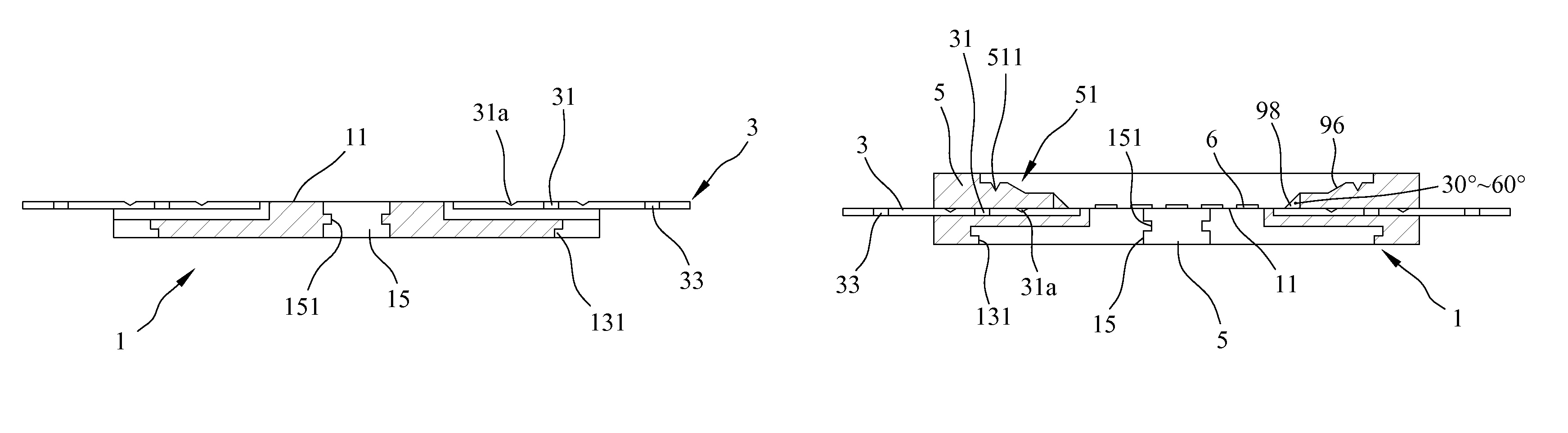
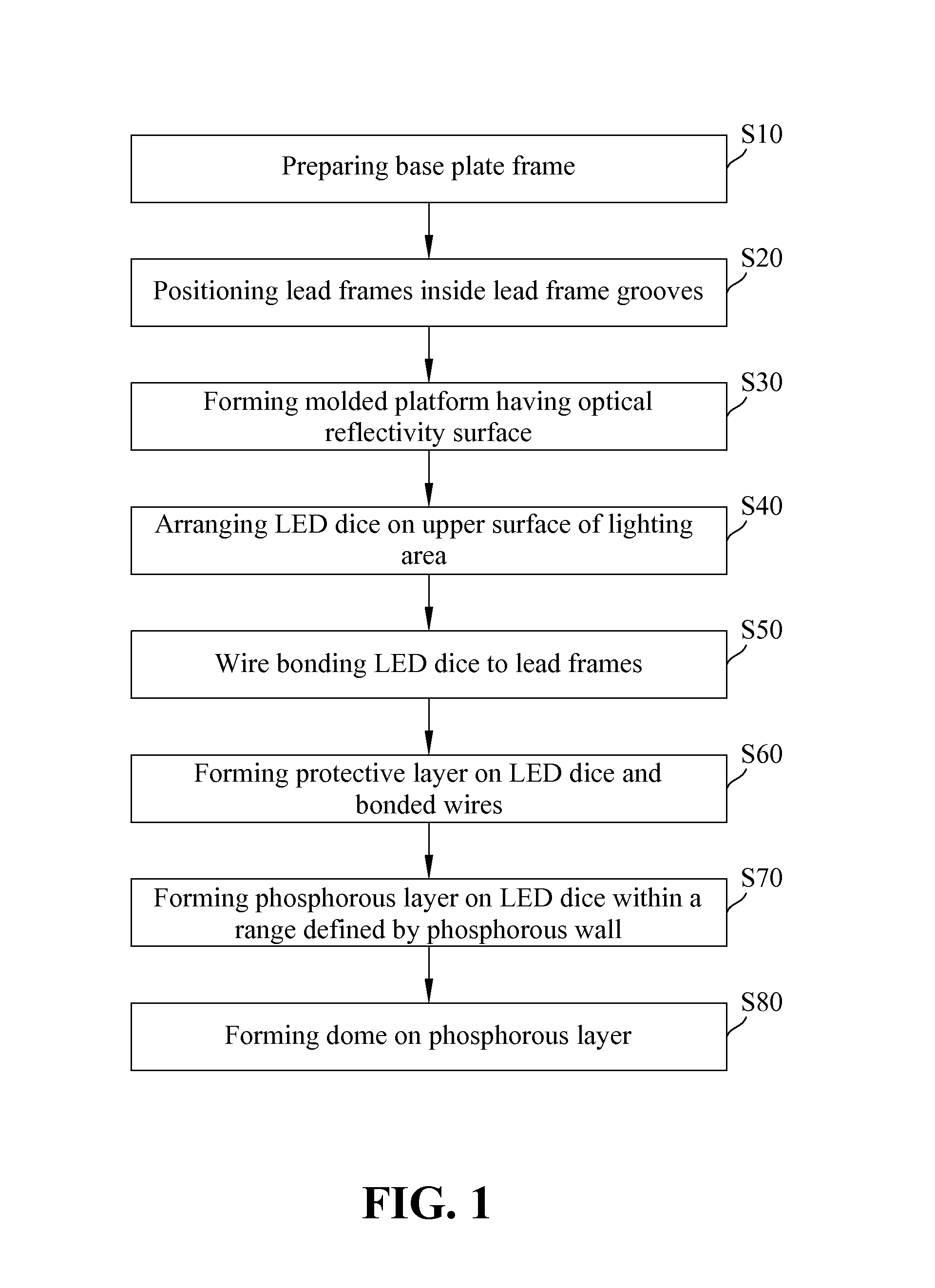
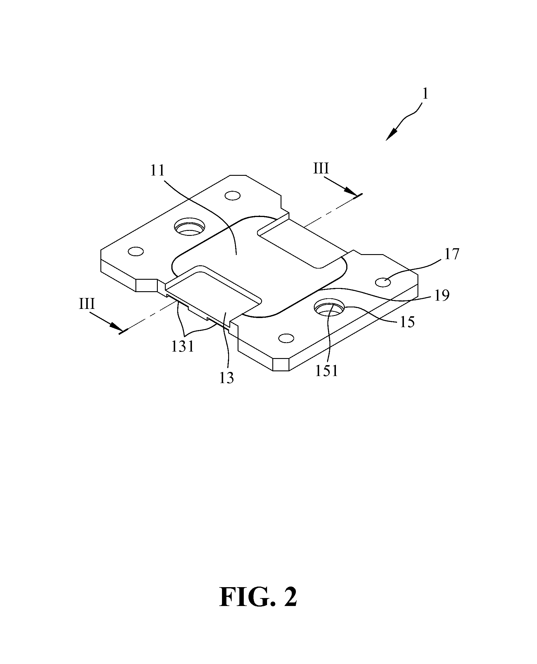
[0027]FIG. 1 is a flow chart illustrating a method of assembling a multi-layer LED array engine according to an embodiment of the present invention. FIG. 2 is a perspective view of a base plate frame of the multilayer LED array engine according to an embodiment of the present invention. FIG. 3 is a cross-sectional view of the base plate frame of FIG. 2 taken along line III-III.

[0028]Referring to FIGS. 1-3, in the step S10 as shown in FIG. 1, a base plate frame 1 is prepared. The base plate frame 1 can be prepared by executing a stamping process, a chemical etching process, a high voltage wire cutting process, or any other suitable processes. For example, the base plate frame is made...


PUM


Abstract

A method of assembling a multi-layer LED array engine is provided. The method includes the steps of: preparing a base plate frame comprising at least one lighting area, and two lead frame grooves; positioning two lead frames inside accommodating spaces defined in the two lead frame grooves, respectively; executing an injection molding process to form a molded platform on the base plate frame; configuring a thin layer of nickel or chromium; arranging a plurality of LED dice in an array form on an upper surface of the base plate frame; electrically coupling the LED dice to the lead frames by bonded wires; forming a protection layer on the LED dice and the bonded wires; forming a phosphorous layer on the protection layer, wherein the phosphorous layer is formed within a range defined by the phosphorous wall; and forming a dome on the upper surface of the molded platform by executing an injection molding process.

Description

BACKGROUND OF THE INVENTION[0001]1. Field of the Invention[0002]The present invention relates generally to a method of assembling a multilayer light emitting diode (LED) array engine. The method of assembling a multi-layer LED array engine is related to a very simple manufacturing process adapted for lowering the manufacturing cost and shortening the manufacturing cycle time of assembling the LED array engine.[0003]2. The Related Arts[0004]Generally, an LED emits light in accordance with the intrinsic characteristic of the solid state semiconductor of the LED. Differing from the light emitting principle of the filament light bulb, an LED emits light when a current flows to the semiconductor PN junction, and does not need to be heated to a high temperature. As such, LEDs are also known as cold light sources. LEDs typically have the advantages including better durability, longer lifespan, lower weight, and lower power consumption. Particularly and more importantly, LEDs do not contain...

Claims


Application Information

Patent Timeline
IPC IPC(8): H01L21/00
CPCH01L25/0753H01L2933/0033H01L2224/45147H01L2224/48137H01L2224/45144H01L2224/48091H01L2924/01015H01L2924/00H01L2924/00014
Inventor HWU, JON-FWUWU, YUNG-FU
Owner GEM WELTRONICS TWN CORP
Why Eureka
Try Eureka