Data recovery circuit

a data recovery and circuit technology, applied in pulse manipulation, pulse technique, synchronisation signal speed/phase control, etc., can solve the problems of essentially difficult feedback-controlled clock extraction circuit and difficult to realize stable clock extraction from light signals whose frequency and phase vary at high speed

Inactive Publication Date: 2011-04-12
MITSUBISHI ELECTRIC CORP
View PDF15 Cites 18 Cited by
  • Summary
  • Abstract
  • Description
  • Claims
  • Application Information

AI Technical Summary

Benefits of technology

[0015]According to the data recovery circuit in the present invention, an effect is obtained in which even when the jitter component is superimposed on the input temporally intermittent burst light signal from the subscriber device (ONU), the data discriminated from the input data in the optimum discrimination phase at high speed can be reproduced and the data synchronized with the reference clock can be output.

Problems solved by technology

The temporally multiplexed signals are burst light signals obtained by intermittently emitting / interrupting the light signals, and hence technical problems specific to input burst light signals occur in the parent station device (OLT) which is a receiver device.
Accordingly, it is essentially difficult for a feedback-controlled clock extraction circuit such as the PLL to obtain high-speed response characteristics.
However, as described above, in the normal PLL system, it is difficult to realize stable clock extraction from a light signal whose frequency and phase vary at high speed.

Method used


Image

  • Data recovery circuit
  • Data recovery circuit
  • Data recovery circuit

Examples


embodiment 1

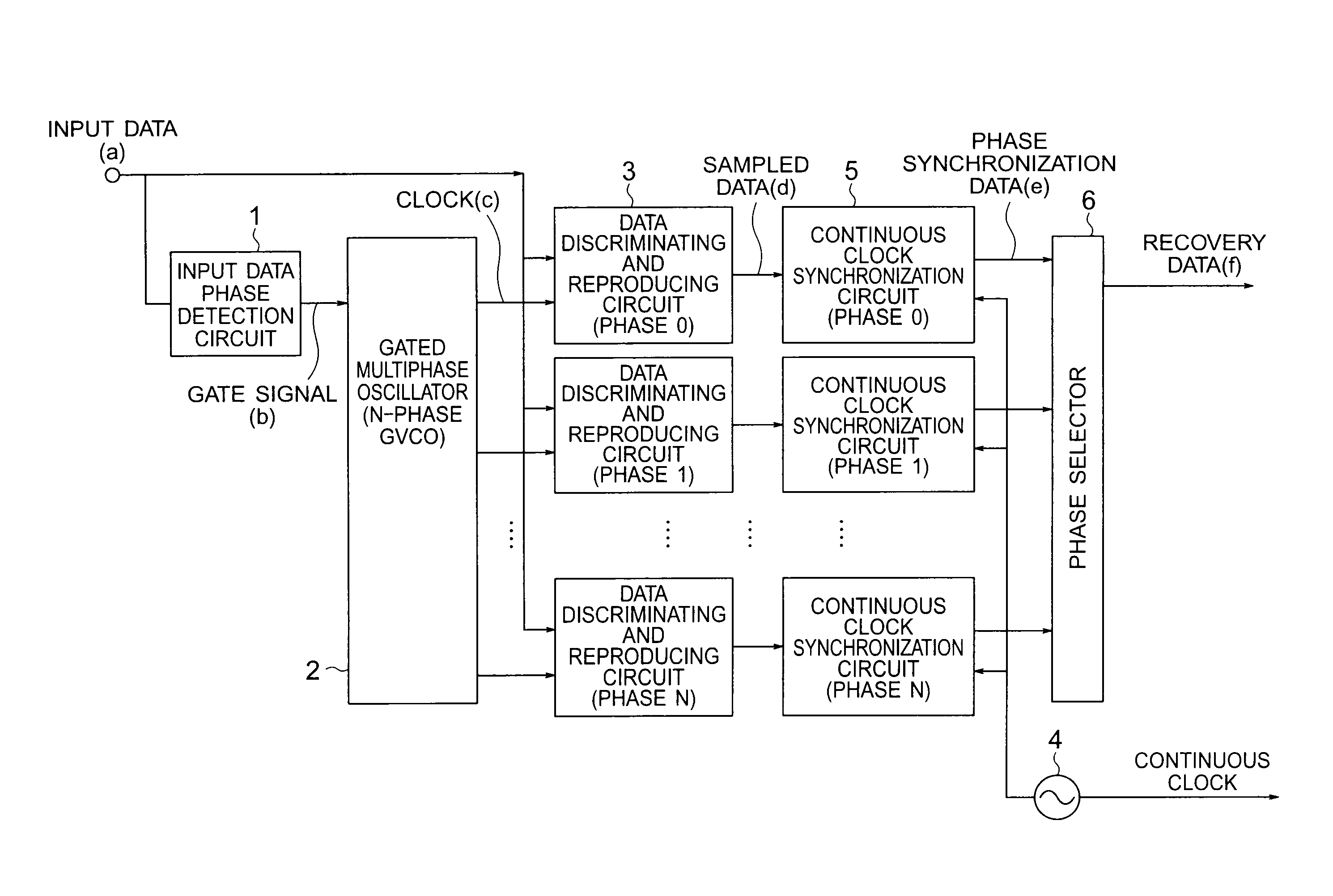
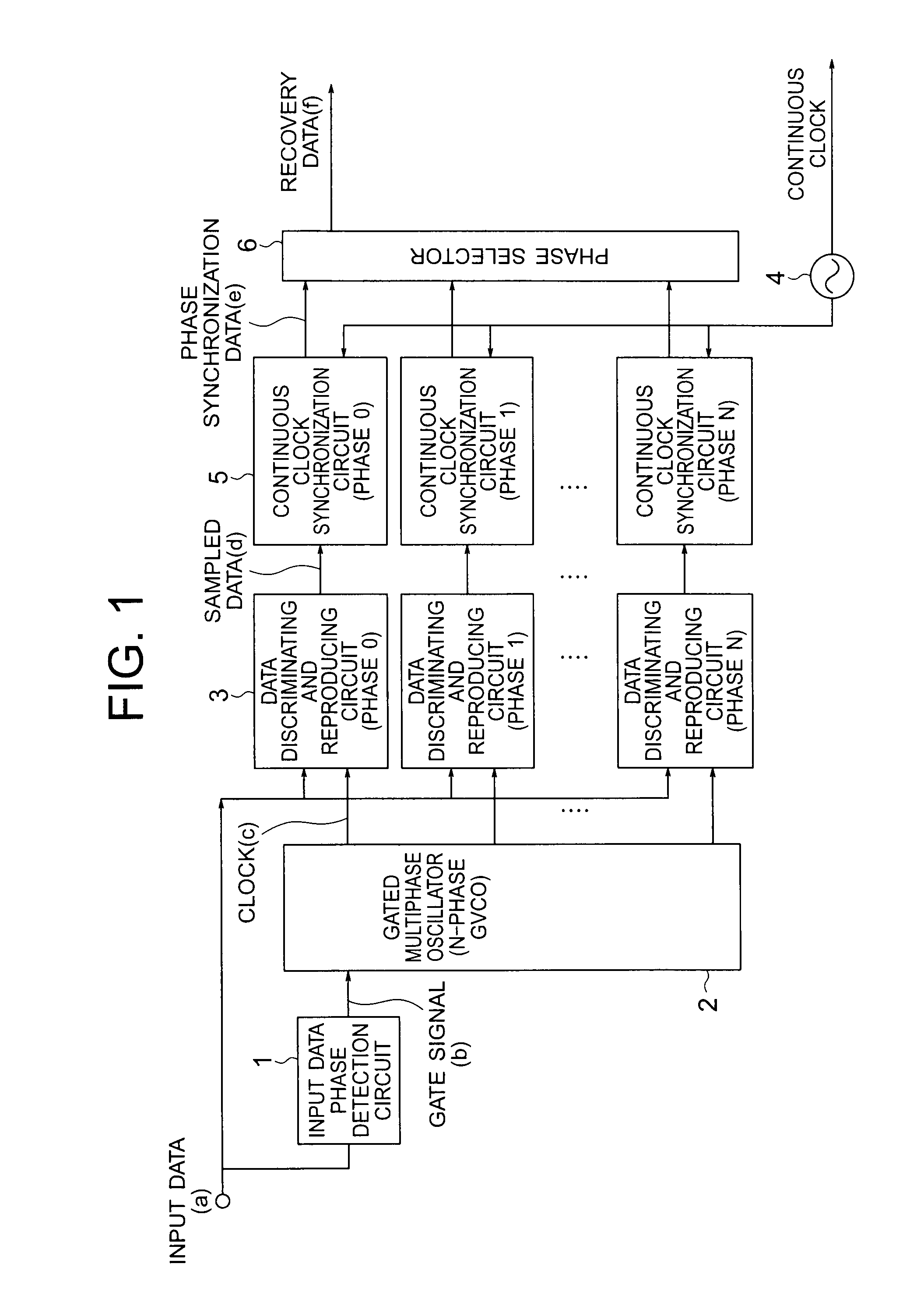
[0026]A data recovery circuit according to Embodiment 1 of the present invention is described with reference to FIGS. 1 to 4. FIG. 1 is a block diagram illustrating a structure of the data recovery circuit according to Embodiment 1 of the present invention. Hereinafter, in each of the drawings, the same reference symbols indicate the same or corresponding portions.

[0027]In FIG. 1, the data recovery circuit according to Embodiment 1 includes an input data phase detection circuit 1, a gated multiphase oscillator (N-phase gated voltage controlled oscillator (GVCO)) 2, N (natural number other than 1) data discriminating and reproducing circuits 3, a continuous clock generation circuit 4, N continuous clock synchronization circuits 5, and a phase selector 6.

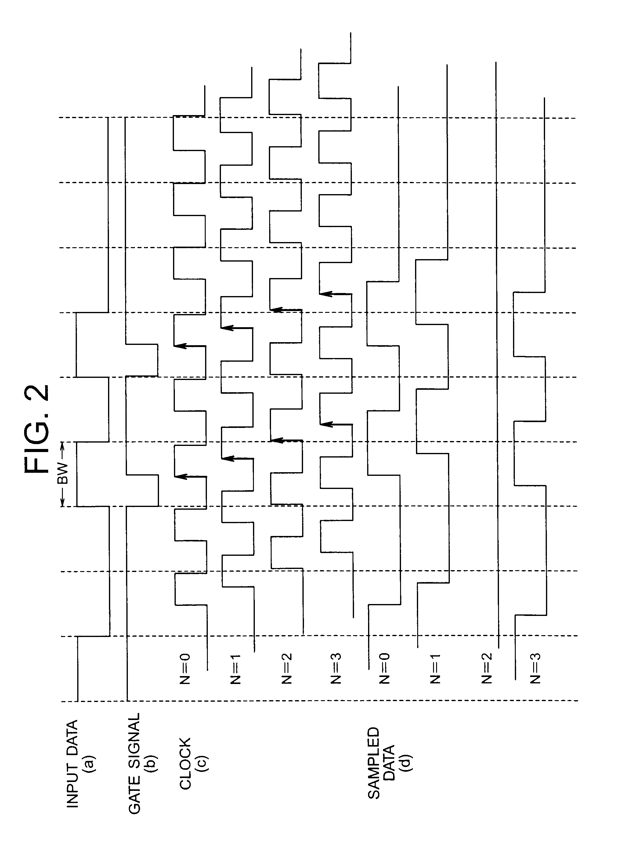
[0028]Next, an operation of the data recovery circuit according to Embodiment 1 is described with reference to the attached drawings. FIG. 2 is a timing chart illustrating operations of the input data phase detection circuit, the gate...

embodiment 2

[0047]A data recovery circuit according to Embodiment 2 of the present invention is described with reference to FIGS. 5 and 6. FIG. 5 is a block diagram illustrating a structure of the data recovery circuit according to Embodiment 2 of the present invention.

[0048]In FIG. 5, the data recovery circuit according to Embodiment 2 includes an input data phase detection circuit 1, a gated multiphase oscillator (N-phase GVCO) 2, N data discriminating and reproducing circuits 3, a continuous clock generation circuit 4, N continuous clock synchronization circuits 5, a phase selector 6, and an input pattern detection circuit 7.

[0049]Next, an operation of the data recovery circuit according to Embodiment 2 is described with reference to the attached drawings.

[0050]Embodiment 2 is a modified example of Embodiment 1 described above. The sampling operation of the input data, the continuous clock synchronization operation, and the phase selection operation are similar to the operations of Embodimen...

embodiment 3

[0055]A data recovery circuit according to Embodiment 3 of the present invention is described with reference to FIG. 7. FIG. 7 is a block diagram illustrating a structure of the data recovery circuit according to Embodiment 3 of the present invention.

[0056]In FIG. 7, the data recovery circuit according to Embodiment 3 includes an input data phase detection circuit 1, a gated multiphase oscillator (N-phase GVCO) 2, N data discriminating and reproducing circuits 3, a continuous clock generation circuit 4, N continuous clock synchronization circuits 5, a phase selector 6, and a frequency / phase synchronization circuit 8.

[0057]The frequency / phase synchronization circuit 8 includes a gated oscillator 81 and a frequency / phase comparator 82.

[0058]Next, an operation of the data recovery circuit according to Embodiment 3 is described with reference to the attached drawings.

[0059]Embodiment 3 is a modified example of Embodiment 1 described above. The sampling operation of the input data, the c...


PUM


Abstract

Provided is a data recovery circuit including an input data phase detection circuit for outputting a gate signal synchronized with a rising phase of input data, a gated multiphase oscillator for instantly generating N-phase clocks based on the gate signal as a trigger, data discriminating and reproducing circuits for outputting sampled data of the input data which are synchronized with the clocks, a continuous clock generation circuit for generating a continuous clock which is a reference clock, continuous clock synchronization circuits for synchronizing the sampled data with the continuous clock and outputting the synchronized sampled data as phase synchronization data, and a phase selector for selecting the phase synchronization data having an optimum discrimination phase with the largest phase margin with respect to the input data and outputting the selected phase synchronization data as recovery data.

Description

TECHNICAL FIELD[0001]The present invention relates to a data recovery circuit for extracting, from input data, a clock synchronized in phase with the input data to reproduce the clock and discriminating and reproducing the input data based on the reproduced clock.BACKGROUND ART[0002]With the rapid growth of the Internet in recent years, a large scale broadband connection in a subscriber access network has been required. The mainstream of a system containing the broadband access network is a passive optical networks (PON) system in which a parent station device (optical line terminal (OLT)) is connected to subscriber devices (optical network units (ONUs)) through an optical fiber. The system structure is internationally standardized in, for example, Non-Patent Document 1.[0003]In the PON system, a time division multiplexing (TDM) method of performing temporal multiplexing is applied as a method of receiving light signals from the respective subscriber devices (ONUs). Therefore, a com...

Claims


Application Information

Patent Timeline
Patent Type & Authority Patents(United States)
IPC IPC(8): H03L7/06
CPCH04L7/0338H04L7/04H04L7/00H04L12/28
Inventor SUZUKI, NAOKITAGAMI, HITOYUKINOGAMI, MASAMICHINAKAGAWA, JUNICHI
Owner MITSUBISHI ELECTRIC CORP
Why Eureka
Try Eureka