Preparation method for an electron tomography sample with embedded markers and a method for reconstructing a three-dimensional image

a three-dimensional image and electron tomography technology, applied in the field of preparation of an electron tomography sample and a three-dimensional (3d) image, can solve the problems of increasing the gap between the specimen and the fiducial marker, increasing the difficulty of identifying the feature, etc., to achieve the effect of reducing the blurring of small features and artifacts, easy tracking, and good quality

Inactive Publication Date: 2011-05-10
MICRON TECH INC
View PDF3 Cites 14 Cited by
  • Summary
  • Abstract
  • Description
  • Claims
  • Application Information

AI Technical Summary

Benefits of technology

[0008]One particular aspect of the present invention is to embed fiducial markers in the ET tomography samples so that the markers can be used for aligning series of tilted 2D images to minimize the blurring of small feature and artifacts in the reconstruction without a change in focus and image shift problems. Thereby, the image analysis system can use the markers that are clearly focused and easily tracked as the references to align series of tilted 2D images. The rotation shift offset is to be compensated for reconstructing the 3D image with good quality.
[0012]The present invention has the following characteristics. The present invention embeds the high contrast markers into the ET samples so that the markers can be used as alignment references for reconstructing the series of tilted 2D images into 3D images. The problems of change in focus and image shift on fiducial markers are overcome and the quality of the 3D reconstruction is improved.

Problems solved by technology

Therefore, the demands for physical failure and materials analysis using the transmission electron microscope or scanning transmission electron microscope are rapidly increasing: for instance thickness measurement, small defect identification, chemical element analysis, etc.
Furthermore, some artifacts, such as amorphous layers and overlapping interfaces in small vias, will become more serious as the dimensions of the TEM sample become larger relative to the ever-shrinking device dimensions.
However, there is a gap between the specimen and fiducial markers.
Therefore, the circular motion paths of fiducial markers are relatively longer during sample tilting compared with each point in the specimen resulting in a change in focus and image shift problems on those fiducial markers during series of tilted 2D images acquisition.
That may make fiducial markers difficult to track or even missing in the worst case, especially with higher magnifications, thicker samples and higher tilt angles.
In addition, the ET 3D images reconstructed from the traditional flat and thin sections are incomplete because the projection images can not be acquired from the range of directions lying close to the plane of the sample.
The lack of information at high tilt angles is referred to as the missing wedge problem.
However, it is not easy for the user to deposit the metal particles (fiducial markers) onto the pillar specimen for feature tracking process.

Method used


Image

  • Preparation method for an electron tomography sample with embedded markers and a method for reconstructing a three-dimensional image
  • Preparation method for an electron tomography sample with embedded markers and a method for reconstructing a three-dimensional image
  • Preparation method for an electron tomography sample with embedded markers and a method for reconstructing a three-dimensional image

Examples


first embodiment

[0020]the sample is illustrated as below. The preparation method of an ET sample includes the following steps.

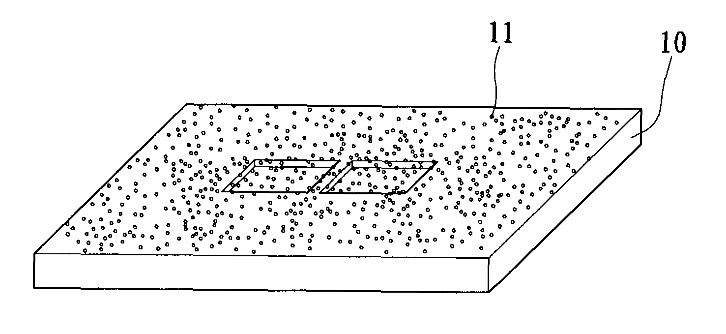
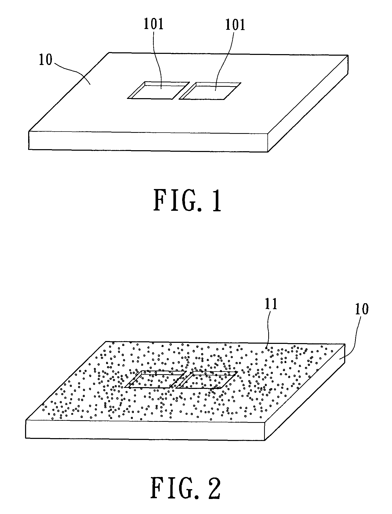
[0021]Step 1: A chip 10 is provided. The chip 10 includes at least one inspecting area. Reference is made to FIG. 1. In this embodiment, the inspecting area on the chip 10 is a target for the analyst to observe and analyze. The neighborhood of the inspecting area is plane (i.e. with no concave structure) so that the inspecting area does not have the concave structures for receiving adequate markers 11, which is the crucial point to improve the feature tracking process and quality of 3D reconstruction.

[0022]Step 2: At least one trench 101 is produced adjacent to the inspecting area. Because there is no concave structure around the inspecting area for receiving the markers, at least one receiving space (i.e. the trench 101) is produced beside the inspecting area. In this embodiment, a dual beam focused ion beam (DB FIB) system is used to mill two square trenches 101 at two sid...

second embodiment

[0030]The present invention also provides the manufacturing method for an ET specimen of chip 10 that includes the following steps.

[0031]Step 1: A chip 10 is provided. The chip 10 includes at least one via-hole structure, such as a metal via that is filled with a barrier layer, such as TiN / Ti, and is not filled with the metal. The step coverage of barrier layers is very important to the electrical performance of metal vias. In this embodiment, the via-hole structure is filled with the barrier layer to manufacture the chip 10. In this case, the via-hole is a concave structure that is used for receiving the markers 11.

[0032]Next, a liquid with the markers 11 is filled into the via-hole structures. The goal of this step is to fill the markers 11 into the via-hole structures and spread on the surface of chip 10 so that the markers 11 and interest are located at the same focus plane during series of tilted 2D images acquisition. The 2D images are aligned by using the markers 11 so that t...


PUM

PropertyMeasurementUnit
heightaaaaaaaaaa
diameteraaaaaaaaaa
diameteraaaaaaaaaa

Abstract

A manufacturing method for an electron tomography specimen with embedded fiducial markers includes the following steps. A chip of wafer is provided. The chip includes at least one inspecting area. At least one trench is produced beside the inspecting area. A liquid with the markers is filled into the trenches. A first protection layer is coated on the chip, and then a second protection layer is deposited on the first protection layer. Therefore, the markers can be embedded into the electron tomography specimen. The embedded markers can improve the alignment process, due to those embedded markers are easily tracked during feature tracking procedure. In addition, our novel invention also successfully provides a modified version of the technique to deposit gold beads onto TEM pillar samples for much improved 3D reconstruction.

Description

BACKGROUND OF THE INVENTION[0001]1. Field of the Invention[0002]The present invention relates to a preparation method for manufacturing an electron tomography (ET) sample and a method for constructing a three-dimensional (3D) image. In particular, the present invention relates to a preparation method for manufacturing an ET sample with embedded markers and a method for reconstructing a 3D image from series of tilted two-dimensional (2D) transmission electron microscopy (TEM) images.[0003]2. Description of Related Art[0004]The rapid advances in nanotechnology and the decreasing size of features in the microelectronics industry result in the need for advanced characterization with high spatial resolution in two and three dimensions. Therefore, the demands for physical failure and materials analysis using the transmission electron microscope or scanning transmission electron microscope are rapidly increasing: for instance thickness measurement, small defect identification, chemical ele...

Claims


Application Information

Patent Timeline
Patent Type & Authority Patents(United States)
IPC IPC(8): G01N23/04H01L23/58H01J37/26
CPCG01N1/28G01N23/2202H01J2237/31745
Inventor LUO, JIAN-SHINGHUANG, CHIA-CHI
Owner MICRON TECH INC
Why Eureka
Try Eureka