Approach for adaptive control of cam profile switching for combustion mode transitions

a cam profile switching and cam profile technology, applied in the direction of instruments, machines/engines, output power, etc., can solve the problems of change in the response time of the oil circuit, early or late cam profile switches, torque jumps, etc., to improve accuracy over predictive algorithms, torque jumps, emissions, fuel consumption and other operational efficiency penalties may be reduced, and more accurate readings

Inactive Publication Date: 2011-05-24
FORD GLOBAL TECH LLC
View PDF6 Cites 28 Cited by
  • Summary
  • Abstract
  • Description
  • Claims
  • Application Information

AI Technical Summary

Benefits of technology

[0001]Vehicles may include engine systems configured to operate a variety of different combustion modes in order to increase the operating efficiency of the vehicle while meeting speed and load demands across the operational range of the engine. In one example, an engine system may operate in a controlled auto-ignition combustion mode a homogenous charge compression ignition (HCCI) combustion mode to achieve higher thermal efficiency and reduce pumping losses relative to other combustion modes resulting in improvements in fuel economy performance and reductions in emissions. HCCI combustion may be desirable or possible only across a particular operating speed / load range. In order to meet demands outside the operating range of HCCI combustion, the engine system may also be configured to operate in a spark ignition (SI) combustion. By operating in both HCCI and SI combustion modes speed / load demands may be met and operating efficiency of the vehicle may be increased.
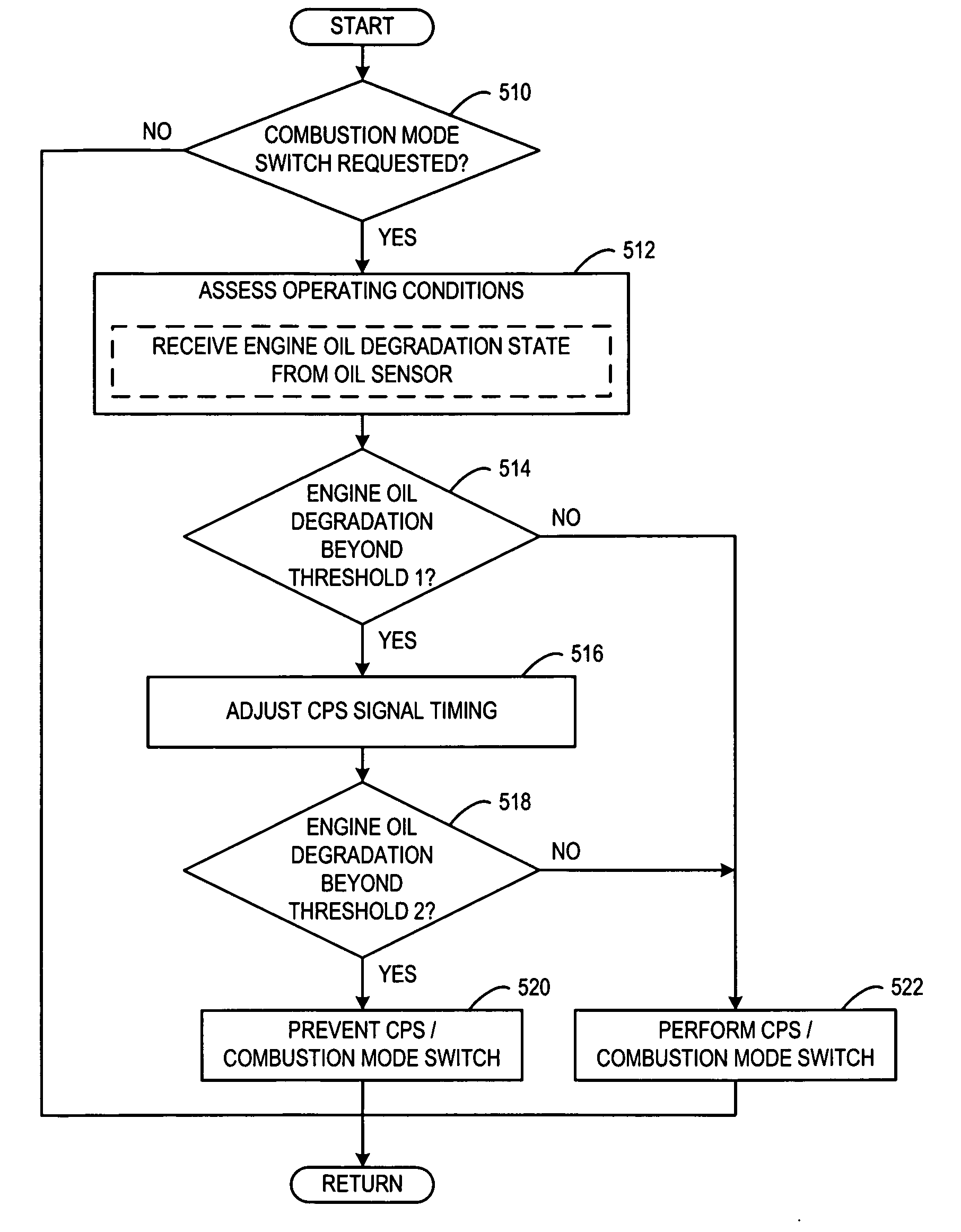
[0005]By adjusting cam profile switching signal timing relative to crankshaft and / or camshaft rotation based on oil degradation using an oil sensor, cam profile switching synchronization may be maintained throughout engine operation even as engine oil degrades. In particular, the oil sensor may provide degradation oil readings that have improved accuracy over predictive algorithms since the oil sensor may measure the condition of the engine oil in real time. In this way, cam profile switching may be performed in a suitable operating window and torque jumps, NVH, emissions, fuel consumption and other operational efficiency penalties may be reduced.
[0006]Furthermore, the signal timing of a cam profile switch may be adjusted based on engine oil temperature as measured by the oil sensor since the viscosity of the engine oil may change at different temperatures resulting in changes in the oil circuit response time. In one particular example, the oil sensor may be configured to measure the temperature of the engine oil directly from rotating components of the engine, such as for example, the oil film of the rotating camshaft. The oil sensor may provide a more accurate reading over a temperature measurement of engine coolant since a temperature delta may exist between engine coolant and engine oil based on the transient dynamics of engine oil temperature occurring more rapidly over the generic coolant based engine temperature. By measuring the engine oil temperature using the oil sensor and adjusting the cam profile switching signal based on the oil temperature, control accuracy may be improved. In this way a transition between combustion modes may be preformed with little or no reductions in operating efficiency.

Problems solved by technology

However, the inventors of the present disclosure have recognized some issues with the above approach.
In particular, during engine operation, engine oil degradation may occur and the engine oil temperature may vary resulting in changes in the response time of the oil circuit to perform a cam profile switch.
The changes in response time of the oil circuit may cause early or late cam profile switches that occur outside the suitable switch window of engine operation.
The early or late switches may result in torque jumps, increased noise, vibration, harshness (NVH), increased emissions and reduced fuel economy performance, among other operational efficiency penalties.

Method used


Image

  • Approach for adaptive control of cam profile switching for combustion mode transitions
  • Approach for adaptive control of cam profile switching for combustion mode transitions
  • Approach for adaptive control of cam profile switching for combustion mode transitions

Examples


Embodiment Construction

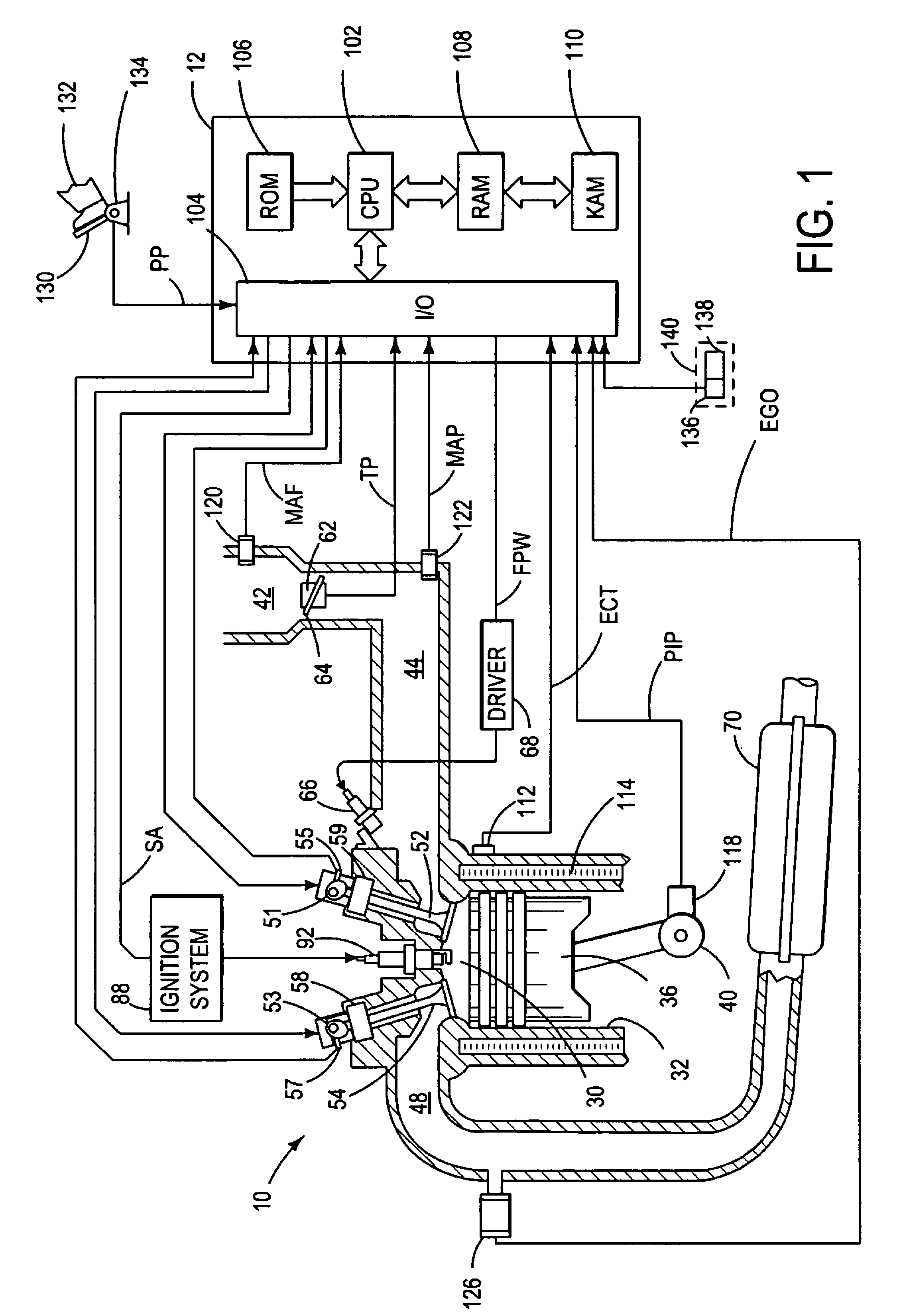
[0014]FIG. 1 is a schematic diagram showing one cylinder of multi-cylinder engine 10, which may be included in a propulsion system of an automobile. Engine 10 may be controlled at least partially by a control system including controller 12 and by input from a vehicle operator 132 via an input device 130. In this example, input device 130 includes an accelerator pedal and a pedal position sensor 134 for generating a proportional pedal position signal PP. Combustion chamber (i.e. cylinder) 30 of engine 10 may include combustion chamber walls 32 with piston 36 positioned therein. Piston 36 may be coupled to crankshaft 40 so that reciprocating motion of the piston is translated into rotational motion of the crankshaft. Crankshaft 40 may be coupled to at least one drive wheel of a vehicle via an intermediate transmission system. Further, a starter motor may be coupled to crankshaft 40 via a flywheel to enable a starting operation of engine 10.

[0015]Combustion chamber 30 may receive intak...


PUM


Abstract

A method is disclosed for controlling cylinder valve switching between a first valve condition and a second valve condition for transitioning between combustion modes of an engine. The method includes adjusting timing of a signal to switch between the valve conditions based on an oil degradation condition from an oil sensor, wherein the combustion modes include spark ignition and homogenous charge compression ignition.

Description

BACKGROUND AND SUMMARY[0001]Vehicles may include engine systems configured to operate a variety of different combustion modes in order to increase the operating efficiency of the vehicle while meeting speed and load demands across the operational range of the engine. In one example, an engine system may operate in a controlled auto-ignition combustion mode a homogenous charge compression ignition (HCCI) combustion mode to achieve higher thermal efficiency and reduce pumping losses relative to other combustion modes resulting in improvements in fuel economy performance and reductions in emissions. HCCI combustion may be desirable or possible only across a particular operating speed / load range. In order to meet demands outside the operating range of HCCI combustion, the engine system may also be configured to operate in a spark ignition (SI) combustion. By operating in both HCCI and SI combustion modes speed / load demands may be met and operating efficiency of the vehicle may be increa...

Claims


Application Information

Patent Timeline
Patent Type & Authority Patents(United States)
IPC IPC(8): F01L1/34
CPCF01L1/143F01L13/0036F01L2800/05F01L2001/2444
Inventor O'NEILL, JONPETRIDIS, THEMI PHILEMON
Owner FORD GLOBAL TECH LLC
Why Eureka
Try Eureka